Hello again! From a few posts ago, I had an idea to build an Arduino knockoff using an RCA1802. But another tech was already doing it (here), and his work is 1000x's better than mine will ever be, even if I worked on it for years. He even picked a better name for the project. Damn!
However, my desire to learn more about computers at a deep level continues on many fronts: Von Neuman architecture, assembler, homebrew PC construction, blinkenlights, and yaddah.
So where to start? How about a timer? Why/why not? No matter what hardware I'll use for this adventure, I figure I'll need a timer that can step through CPU machine cycles and see if my code is working. Marvey let's build that.

To this end I found a great series of vids on youtube from Ben Eater where he fabs a simple 6502 PC (that's CPU used in old Apples and other early PCs) using breadboards--his "getting started" webpage is here. This is a complex subject, but the author explains things so clearly and patiently that even a tinitous distressed, OCD burdened, over the hill rock and roll guy like me can follow along.
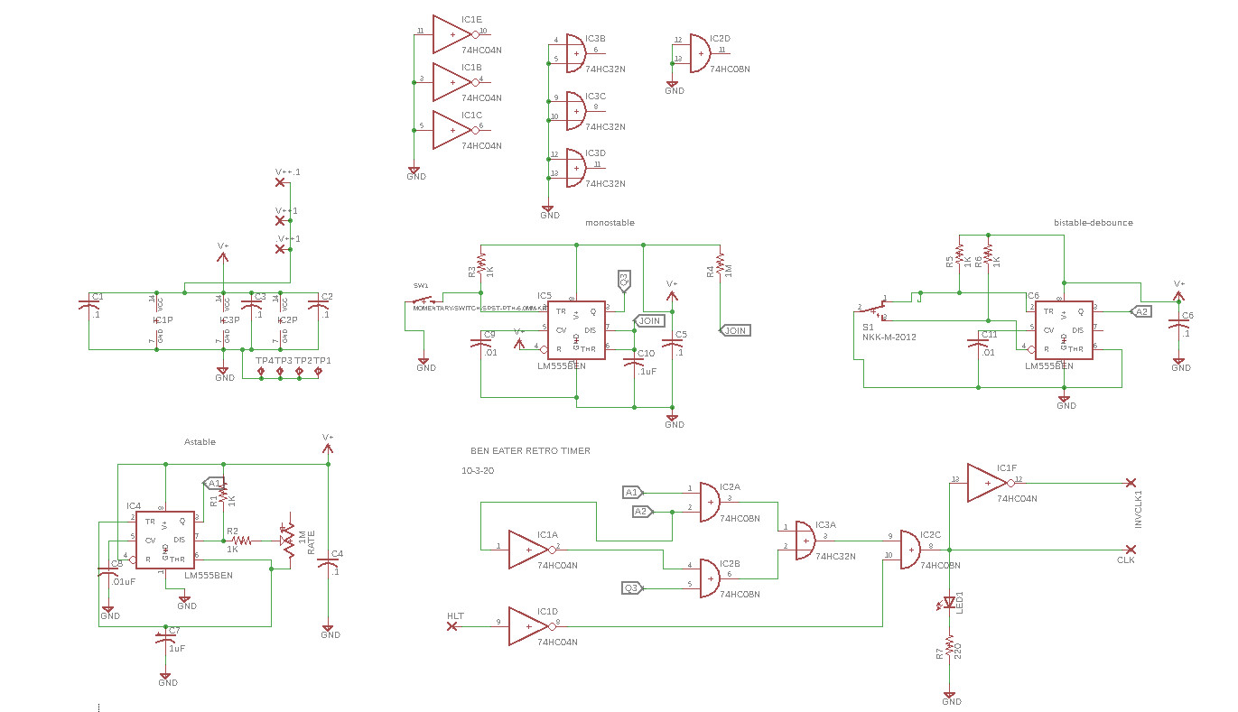
In addition to 6502 madness, the vid series has a very good series of explanations about how the venerable 555 timer works--part I is here. Mr. Eater uses 3x 555's in a monostable/bistable/astable timing board for his own 6502 machine language "Hello World" project.
Let's motorize this pursuit! I laid the Eater timer out in Eagle--as I've said many times, I can't breadboard to save my life and slapping together a gerber/getting it fabbed/getting it built is affordable and in the long run, seems more expedient.
For this timer board--didn't work the first time, I made a few dumb mistakes, but 2nd go at it, the PCB works 100% as far as I can tell; he's the schematic:

A couple of useless build photos:


It works. I have a gerber for this....if you want it, ready to send off to your favorite fab shop, comment below, we will figure something out. Important! if you build this board make sure to tie HALT to ground to allow the circuit to work reliably, or wire in a switch between 5V (off) and Ground (run) to HALT. For my build I ran a 22 gauge jumper from GND to halt which is not shown in the photos above.
OK now what? I bought a kit for the basic Eater 6502 hardware kit (here, scroll down the page) and this PCB for it (here, there are others) but while I'm waiting I figure I can get my feet wet with a 6502 emulator. There are lots online but I really liked the one here; it's simple--download the js and html stuff, stick the files on your PC, open with Chrome, and you're off.
Using that, with help from some vids, I created my first assembly language program--for me, the first one ever. Who needs hardware?
OK the code below paints the background of the emulator's screen in whatever (limited) color you choose.
Assembly language in general is unlike anything I've coded with before, but with assembler we're baking things down a very simple form, and as a reductionist, that's A-OK by me. Once I got the hang of this what you see below wasn't that hard tp figure out, and I figure assembly for relatively simple processors like this, for certain things, might be easier than C? No mallocs, crazy pointers, C++ objects etc. anyway. Just goofy 3 letter codes, right?
So here is the code:
LDX #$02 ; load h02 into X
STX $11 ; put X into special RAM MSB
LDY #$00 ; load offset Y 0
LDX #$02 ; load h02 into X
STX $11 ; put X into special RAM MSB
LDX #$00 ; load h00 into X
STX $10 ; put X into special RAM LSB
LDA #02 ; color of pixel to draw
STA ($10),Y ; indirect memory addressing 0x0200 to get to 16 bits…..
JSR draw1
LDX #$03 ; load h03 into X
STX $11 ; put X into special RAM MSB
LDX #$00
JSR draw1
STX $11 ; put X into special RAM MSB
LDX #$00
JSR draw1
STX $11 ; put X into special RAM MSB
LDX #$00
JSR draw1
INX ; increase X register by one
STX $10 ; put that into RAM LSB
STA ($10),Y ; store A register (color) to screen
CPX #$00 ; compare, is X at h00?
BNE draw1
RTS
I am not sure the code above is as optimal as it could be but it works.
Going forward: Next up is build the Eater homebrew 6502. To further flesh this out I have some ancient Analog devices parallel A to D's, it would be interesting to see if I can get those going with the home brew 6502 circuit.
OK which begs the question: Why can't I just use an Arduino to learn how computers work at their deepest level? Anything I can do on a 6502 can be done on a modern CPU, right? But the 6502 makes me feel as I am starting out simple. And best of all: For me, it's like, well, you know: all new, no matter what.
OK that's it, until next time don't breathe the fumes.


No comments:
Post a Comment