Improving the SEM Attenuverter

 Hello again! A few years ago I designed and laid out an Oberheim SEM inspired attenuverter, posts are here and here.  

Never being 100% happy with anything I do, I redesigned the main board to give better user control of bias inputs. Today's post goes over the updated circuit design.

Improved attenuverter module in FRAC format


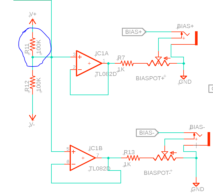
Let's look at the bias input buffers found in the initial design:

Original design

First off, the 2018 design has a glaring typo: pins 3 and 5 need +5V at input, not 0V, so I don't know what I was thinking with a 100K/100K voltage divider between the rails. I used 47K for R11 in the actual build, but still, the circa 2019 schematic had this glaring mistake.

Here is the new design:

Update!!

Besides fixing R11's value, the Bias pots now control levels found from the CV **or** the signal found at "Bias+" and "Bias -". This meant the user has greater flexibility for controlling the input bias CV using the B100K pots.

The rest of the schematic remained unchanged.

Another issue was that the PCB was tall to comfortably fit into a Frac case. This is fixed in the gerbers found on the PCBWAY project page, here, and the github for the build, here. If you want to build this attenuverter for Frac, make sure to download and fab the standoff daughterboard for the CTPOT, it is needed for the layout.


With the PCBs trimmed to size it was now a matter of populating it.   

The latest Attenuverter PCBs were provided by this blog's honorable sponsor, PCBWAY.  I would be very grateful if you could check them out for your next project.


A daughterboard is needed for the center tap pot--read more in  this previous post.  


The center pot shaft had to be shorted using a Dremel tool.

ready to test!

I like it when it works the first time!

What's next?  I have new RP2040 dev boards to experiment with, more on that next time. I also want to design a front panel for this attenuverter for Eurorack....(update--Euro port of this asttenuverter is done and works--go here).

Until then, don't breathe the fumes!

Cloning the Moog CP3 Mixer

I read that the secret sauce that makes the Minimoog/Moog Modular sound so damn good is the subtle distortion introduced by its audio mixer.  True? False? 

Let's build one and find out! 

For this post I laid out three PCB's the capture Moog's legendary CP3 design, got them fabricated at that blog's sponsor, PCBWAY, then built a Eurorack format skiff clone:


CP3 (io) CLONE WARS

Let's go!

I found the original Moog CP3 schematic--looks simple enough--here.  

I captured the CP3 schematic, then laid out PCB's using Eagle; to save space I used 3 PCBs stacked in a skiff setup: front panel, a board for pots and jacks, and the mixer PCB.  

Front Panel is designed to Euro spec


100 mil edge connectors were used instead of hookup wire...."skiff"
 depth


Next I sent the gerbers off the this blog's trusty sponsor, PCBWAY; they were back in a jiffy, good to go:

Thanks to PCBWAY for sponsoring AudioDiWHY, you can help this blog by checking them out.

Most of the CP3's components were commonplace and could be found in my junk box, but I had to order a some pots from Tayda, and I found 3392 and 4058 transistors for about 70c each from Mouser.


On to the build....  

Very straightforward--the entire process took about two hours.

The board accommodates the CP3's original 3392/4058 transistors, which seem a bit rare, as well as easier to find 2N3904/3906's. If you build this CP3 clone, use 2x NPNs and 2x PNPs.


I built two CP3s; one used 3904's/3906's; the other 3392's and 4058's "NOS" components.

The 2N3904/06 build worked flawlessly the first time. Joy! However, the 3392/4058 version didn't work at first, I thought it was my layout, since the pins on 3392's are different than the 3094's, but no, that wasn't it; turned out, Mouser put the wrong part in the bag:


What is a JCJ111 anyway? A Jfet, I think. I called up Mouser, they were very nice about this, and sent me 5 3392's to replace the one transistor that was misshipped. Hey, it happens right?

I replaced the JCJ111 with a 3392; afterwards, the NOS board worked.  

Overall this was a pretty easy design to capture, lay out, and build. 

If you want to build one, get PCBs, BOM, gerbers, eagle files, PDFs of the layouts, etc., from PCBWAY community (here) and/or my github page (here).  

Which transistors to use? 

To my ears, the 3904/06 version sounded a bit better than the NOS unit--a bit less noise, with the same pleasing distortion when levels were turned way up.  

So--if you build this, save time, money and trouble and just use 3904 and 3906's. 

Using the CP3

The "click filter" is a passive low pass filter in the CP3's signal flow, not sure how much I will use it, but it indeeds knocks a sizable portion of the high end off the circuit's outputs.

I used tiny trimmers for the input level adjustments to save space, that makes the panel a bit crowded, but hey, in the Eurorack world, things get crowded.  

Overall, the CP3, to my ears, does indeed add Moog's signature Minimoog/System 55 distortion to a patch: subtle, warm, and fat sounding, especially with ramp waves. 

I am happy with how this DiWHY project came out and will use these 2 mixers a lot going forward.

If I get time I will record before/after wav files, photograph scope shots of distorted waveforms, etc., but right now it's back to the day job (post Covid?) and on to new things.  

CODA 

Still more analog, less digital, next time. After many long months, I am going to try to fix a few problems with an attenuverter circuit from several posts ago. See ya.

Euro VCA--"Bay Area Modular" Group Build


#include <stdbool.h>

bool real_nerds_dont_socialize = false;

Every other week I meet up with the fine audio geeks of "Bay Area Modular". Here we discuss life, liberty, if Behringer  is modular methodone, and the final -2db off the noise floor.  

An ongoing project/meeting recently completed: members proficient at audio DIY showed the less civilized members how to lay out and build a complete Eurorack synthesizer module.  

The build chosen was the "Farm VCA" from the website here (the original post from a server in Japan appears to have been taken down...but its open source design lives on....) 

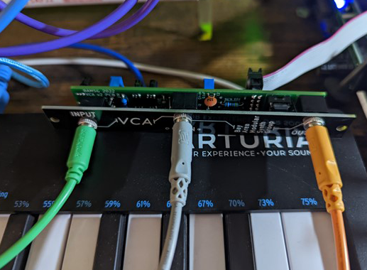
This time we go over the successful outcome: a simple EuroRack Voltage Controlled Amplifier.

The two boards (main board and front panel) were laid out in Kicad 6.0 by Elton at Otter Mods and the rest of the group.  

My sponsor, PCBWAY, generously donated the PCB fabrication.

(Great news--except for a blown up trimmer--my fault!--the module worked first time, no kludges, no rewiring, no fixes.) 

Here's the finished module: 


Wrong trimmer--should be 100K, not 100R. Oops, blew it up during my intial test, but it was easily replaced.


The group laid out the board with components occupying both sides of the PCB to get the design into a 3HP configuration


Elton testing the module in his rack

Works--Rack em!


Get the schematics, gerbers, BOM etc., from PCBWAY's project page, here.  

More analog hardware?  Less Digital?  Less C nonsense?  Bring back Arduino? We can only hope.....See you next time! 

AD9833 C Library Port for RP2040 MCU

For the 10 or so of you out there coding audio projects using C and the Raspberry Pi Foundation's RP2040 microcontroller, good news: the world has yet another C library for the AD9833 function generator IC.  

I'll use the library in upcoming projects, but for now, the RP2040 AD9833 C library can be found on github--get it here.

Test the library....

This was one of the more complicated embedded C coding exercises I've taken on to date.

The library does far more than its predecessor (blog post here--github here--Atmel 328 version).  

Progress? I put descriptions of what each function does in the AD9833.h file, and main.c has routines to test the methods using the UART serial protocol (see the last post--here).

Wiring on the bench for the library tests.....

I only had one issue while coding, but it was a big time-waster and took a day and a half to figure out.  

All the functions for register0 for the AD9833 IC worked, but any time I tried to use anything saved in register 1 I got nothing--like the entire register was smoked.

It turned out I was using SPI mode 0 initially, but the AD9833 needed SPI mode 2 to operate.

Because of this mistake, any SPI MOSI transmission that tried to use a 1 as the MSB didn't work--for AD9833, that one means you are sending data to register 1.

I figured this out (finally!) by comparing a logic trace from an Arduino Uno R3 <--> AD9833 with a sketch running the AD9833 Arduino library that I wrote previously, the Arduino C library is available here.  

I then did similar a logic analysis of my RP2040 library wired up in the manner you see above. 

When comparing the logic analyses, it was obvious that my PR2040  code was trying to use SPI mode 0. 

Why?  Dumb bug!  

I had an if/then statement error in my previously posted RP2040 SPI library  (here). Simple fix once I spotted it.  

Lesson learned: use your logic analyzer to debug code issues!! 

Early and often!!

UPDATE 10-1-22 I copied the library and examples to a new project and it wouldn't compile!  It used to! I was getting multiple definition errors--hello?  I was adding #ifndef--etc in the h library files correctly. So that wasn't it.

After some cursing, I made a lucky guess: adding the static keyword before the global array declarations in ad9833.h and uart.h made the error go away.  

Best I can guess, some part of the toolchain--maybe GCC?--was recently updated, the old version was correctly inferring which variables were "extern's" vs "static", but the new version couldn't or didn't want to make this inference. 

I read that correctly implementing static vs. extern keywords in C is tricky....Good video on static variables in C/C++ is here 

After reading up on these keywords and then watching the video, I was a bit surprised the linker didn't throw errors linking initial versions of the ad9833 library and examples code. 

Anyway, I have updated the github reposiotry for the library with these changes. It now compiles again without issue.

As a side note: I also added to github a couple of bin2hex.c functions, as well as a python script that can be used to craft binary to frequency tables, which I figure I will need for future projects. 

Get those here and here.

Next time it's back to hardware. Analog! I'll be hitting my generous sponsor PCBWAY up for more boards soon and post the results, working or not. For example, I have a commuinty Eurorack VCA almost built and ready to post. Coming soon! Until then don't breathe the Sea fumes. 

Testing Embedded C Libraries--Who Cut the UART?

Highty Ho Boys and girls, more embedded C fun in the land of audioDiWhy. 

I'll be back with more hardware builds next month, but for now I continue to experiment with embedded C code for the Raspberry Pi RP2040 processor.

This week I ported an  AD9833 library I wrote for Atmel MPU's to RP2040. 

It's ready to test--however the new library has 25 methods and counting. How do I test the library without having to rewrite and recompile main.c over and over?  

I used UART.  This is the protocol that flowed between your 80's era PC clone and a <15K baud dial up modem. Useful things stick around; UART is simple, well documented, and supported in some manner on many computers and development boards.  

An informative webpage regarding how UART works is here.  


GET IT WIRED UP

RP2040/pico SDK makers can configure serial via USB configured through CMakeLists.txt but I found serial UART from my RP2040 developpment board simpler and more accurate once everything was set up correctly.

I am using a Raspberry Pi for sending and receiving UART serial communications from development boards. Setting a Raspberry Pi 4 up for serial wasn't as simple as I thought it'd be, but the video here helped. 

To wire it up:  

I created a 3 conductor wire with expando sleeving and dupont connectors for TX > RX, RX > TX, and GND < > GND. Note that you must connect ground between the host and the development board for any of this to work.

Assuming you are using my code: there are different UART pins on the Pico; you have to use the right ones. I used GPIO "0" or Pin 1 for RX; GPIO "1" or Pin 2 for TX, on the PICO. This conforms to defaults set in pico.h in the SDK.

On the RPi, I used GPIO pins 14 for TX and 15 for RX.  This is UART0.

On the RPi4, install minicom if it's not already there.  Settings are 115200 baud rate, and 8n1

To this end, make sure your CMakeLists.txt has "I want UART for serial, not USB" set correctly:

#control USB output--1 means on.

pico_enable_stdio_usb(${PROJECT_NAME} 0)

pico_enable_stdio_uart(${PROJECT_NAME} 1)

Wiring up the Pico for UART....


I use SSH to get to this Raspberry Pi SBC and then use Minicom as the terminal program


USAGE

UART and so on in the Pico API are documented here. This is a subsection of the PICO hardware API docs, here.

You can get the UART.c and UART.h files used in this post, ready to drop into your project, here. The basic use case for the library is documented in the library's UART.h.  

Here is basic syntax:

/*

put this in endless loop in main

READ_UART_BUFFER; 

// trap a matched string you type into your terminal program:

printf("%s\n",uart_buffer); // show what you just typed

    if (UART_READ("REBOOT"))// reboot right from minicom!!!!

        {

        reset_usb_boot(0,0);  reboot PICO

        } 

    else

        {

        // any other entry into the buffer does whatever is coded in              //here.

        }

    }

*/

AD-WHY? C WHAT? DEVWHAT? 

Why do any of this at all? (the audiodiWhy mantra....)

The AD9833 is a function generator chip--it has a reasonably wide frequency range (.1hz to 12.5Mhz), multiple waveforms, reasonably low noise, 2 registers for phase, sleep modes, and so on. I hoped to build a volt/octave FM synthesis board and other waveform generators using AD9833's along with  RP2040 development boards; for that I figure I need a working AD9833 library.

There are already Arduino libraries for the AD9833 IC (here), and I assume other popular microcontrollers, but maybe not for the RP2040. (Really? Not sure. I didn't en endlessly google RP2040 C AD9833 or whatever....so maybe a working PICO <> AD9833 C library was already out there? In any event, it wouldn't hurt to roll my own as a learning experience....)

A few mornings later the library was written and I was ready to test...so I started modifying main.c to test each method.

So:

tri(); 

after recompiling changed the waveform at output of the AD9833 to a triangle.  Works!  

Next in main.c I added

squarehalf(); 

and recompiled; this altered a square wave to .5* of the frequency found in either frequency register.  This worked as well.

phase1(1300); 

along with recompiling put a 14 bit phase value into the IC's phase 1 register.  That didn't work quite right so i tweaked it, recompiled, and after that yes, it worked.

You get the idea.


AD9833 Breakout Board

With all of these methods to test, modifying main.c, then re-compiling, then re-uploading to the Pico over and over became tedious.

How could this be streamlined?

For inspiration I didn't go out in nature--I didn't breathe the fumes--I didn't even talk to fellow geeks.  

Instead I turned to youtube. Specifically the video here

The content creator uses a UART serial stream to turn off and on LEDs on a Pico dev board, but as he mentions: there are other use cases. Testing libraries could be one of them.

So: I got this going on my bench. 

After configuring a Raspberry Pi 4 I had lying around, I wired the UART TX and RX to the RX and TX on the Pico following the steps at the beginning of this post.

Finally I SSH'd from my Ubuntu bench virtual machine to the Raspberry Pi, then once shelled in, ran minicom. Minicom of course can send data over serial by typing characters into its terminal, which I did to kick off each function under test.  

CODE ME UP ANNIE!

In a header file I called uart.h, at the top of the file, I declared a 1K global array, then wrote a global macro to compare a scanf statement to the contents of the newly created buffer. This almost straight out of  the aforementioned "low level learning" video, so again, if you've made it this far in today's post, you should consider watching it, the video is here.

// global buffer for uart reads

char uart_buffer[1024]; 

//define macro for endless loop in main

#define READ_UART_BUFFER scanf("%1024s",uart_buffer) 

//test to see if string X is in buffer. 

//Do whatever is in curlies {...} if there is a match

#define UART_READ(X) strcmp(uart_buffer, X)== 0

in main.c's main loop, I trapped a match between a string and what is in the uart_buffer.  

while (1 < 2) {

    READ_UART_BUFFER;

    if (UART_READ("TRI")) //gen tri wave

        {

            AD9833_Tri();

            CNTL_SEND; //macro to send via SPI the control uint16_t 

        }

AD9833_Tri() was supposed to change whatever waveform the AD9833 was generating to a triangle. Hooking the IC's output did the sine change to a triangle? Not at first, so I stopped and worked on the method--and no need to change main.c--and quickly had the function up running.

Next I expanded this paradigm so I could extract parameters from the serial data. UART only sends strings between systems, so, how could I trap numbers (decimals) to use as function parameters?  

For example, I wanted to test the AD9833's  FREQ0 register with 0x4000 0x4000.  Right after, I wanted to test 0x4000 0x5000.  

I could have written switch statements, or a lot of if ()'s in main.c.

Instead I created a new file, uart.c and wrote functions based on strncmp--on a match, the functions  extracted the ASCii style numbers; turned them to decimals and sent the uint32_t's to a function under test.  

Here's the code:

uint8_t compare_strings(char *a, char *b, uint8_t len)

{

   uint8_t x = 0;

   if ((strncmp(a,b,len))==0)

   {

     x = 1;

     return x;

   }   

   else

   {

      x = 0;

      return x;

   }

}

//////////////////

uint32_t dumpleft_conv2dec(char *hi, uint8_t chopleft, uint8_t digits)

 {   

    uint8_t i, len = 0;

    uint32_t result = 0;

    char *x = hi;  

    uint8_t count = 0; 

    count = chopleft;

    do

    {

          {        

        *(x + count - chopleft) = *(x + count);

          }

          count++;

    }

    while (*(x+count) != '\0');


    //deal with end of string 

   if (*(x + count) == '\0')

    {   


        *(x + count - chopleft) = '\0';         

    }


    //turn ASCII numbers into a decimel number

    for (i=0; i< digits; i++)

    {

      result = result * 10 + ( x[i] - '0' );

}

        return result;  

 }

compare_strings matches string array *a to *b from left to right, up to len characters.  If there is a match, it returns a 1. dumpleft_conv2dec then strips whatever characters I didn't want from the left side of the string (chopleft), and turned the rest of the string into a decimal value of length digits (keeping in mind that char "1234" did not directly translate to dec 1234--ASCii uses different codes for decimal characters!) 

 Now I can type FRQ02000 into minicom and main.c finds a match, gets rid of the "FRQ", and turns 02000 into decimal 2000.  

From here it's trivial to use this as a parameter to test a function:

 char f[4] = "FRQ"; // this has to be +1 greater than # of chars when creating array    

        if (compare_strings(uart_buffer,f,3)) // compare first 3 chars

        {

            uint32_t rez = 0;

            rez = dumpleft_conv2dec(uart_buffer, 3, 5);

            AD9833_LoadFreq0(rez);

           FREQSEND; //macro to send via SPI 4x freq bytes to register

        }


Ha! This worked! 

THE BIG LIMITATION

Putting a scanf() into the loop in your main.c means your loop will stop at the scanf(), waiting for input. This means your main.c loop won't loop. 

This worked for testing this library, but for other applications, say, reading a rotary encoder, probably not--you need your loop to loop! For that I can see using an interrupt and not scanf() when UART data comes in. 

I will probably experiment with modifying the code to use interrupts in an upcoming post.

ARDUINO AGAINO?

Another use for the UART paradigm is to run a high power processor on the back end and use something TX ready, like a Pro Micro, on the front end/user interface. The Ardunio handles the switches, pots, LEDs and OLED displays. 

As long as the end user can tolerate a brief delay--for example, a waveform that takes 100-200ms to change--an Arduino could send the same ASCII strings to the backend processor used during testing--we already know it works!

However, I have a faint recollection that RX and TX commuincation step on Arduino bootloaders--so you can't program an Uno R3 with the RX and TX pins connected to something sinking current.  Why do I think that? I don't remember, and maybe I'm wrong.  I hope I am. I guess we'll see.


Embedded C--Recursion, C Macros, Stupid Stack Tricks, and a Clever Hex to Binary Function

....if that blog post title doesn't make you want to watch paint dry then what will?

Working on an AD9833 library for RP2040? Maybe next post....getting there....


Onward!

I am always trying to sharpen my Embedded C skills, the programming language I primarily use to program MCUs.

This week I continue to work on an AD9833 SPI library (already written for Atmel 328--here), ported to work with 32bit MCUs like the RP2040. 

Today though I went down the rabbit hole, trying to find the simplest function for hex or decimel to binary conversion for printf()'s 

Why? Why not?

A lot of embedded C programming (and digital electronics in general) comes down to sending 1's and 0's from one component to another. 

Doh?

However at times I can visualize what 0b0001011001110111 is going to do when viewing the dataflow on a logic analyzer 

Something like 0x1677 doesn't fire up my neurons the same way. 

Is that just me? A lack of experience with hex? Maybe. 

Unfortunately, C has no easy means I know to printf() a binary number--hex, yes, decimel, yes, floats, yes, but binary, no. 

So, it's a matter of finding a hex to binary function I like online and stealing it? Sure. 

I found plenty of C hex to binary functions online that start with a string array and produce binary output as a string (for instance, here), but for what we embedded C folks work on (mostly numbers, not a lot of strings) that's not much help. 

I needed the input parameter to be a number, not an array.

After a bit more searching I found a brilliant little recursive function--original post is here.  

It's only 4 lines of code!

#include "hex2bin.h"

void hex2bin(int16_t h)

{

if (!h) return; 

hex2bin(h>>1);

printf("%d",h&1);  

return;

}

It works!!  

Orig number:  0xdc or 7618976
11011100
  

How does this wonderful fragment work?  At first I didn't care, don't look gift code in the mouth? 

But then it started to drive me crazy. I could see no logical reason why bin2hex() should not present its output in the wrong order!

Why did I think that?

once you run this

h  >> 1 

The number you're converting (say, x = 200) decreases down to 0, so you're done. 

But, if you don't recurse, the printf()'d output shows an incorrect binary value because it's backwards; for example, 0b1100111 is output when you wanted 0b1110011.  

However the 4 line fragment doesn't do this--somehow it prints the final result in the correct order.

But how, Scotty, how?

Sadly Cap'n Kirk's C skills were shit, but could he kick ass with Esperanto....


Turns out, it's a call stack trick--using Codeblocks, in debug mode, with the stack and watches debug windows visible (good tutorial for Codeblocks C debugging is here), it was easy to see what was happening.

I created a simple (and very similar) function that subtracts 20 from "h" which in this case is 220:

void hex2bin(int16_t h)

{
printf("h is: %d \n",h);
if (!h)
{   printf("IN RETURN. H is %d \n",h);
    return;}
else
{
    printf("not there yet \n");
}
hex2bin(h - 20);
printf("h is: %d \n",h);

}

The stack looks like this--the call stack loads its data "upwards"--so the values of h - 20 appear in reverse order:


Here is the output from the hex2bin function, called from main.c, with a parameter value of 220:

0bh is: 220
not there yet
h is: 200
not there yet
h is: 180
not there yet
h is: 160
not there yet
h is: 140
not there yet
h is: 120
not there yet
h is: 100
not there yet
h is: 80
not there yet
h is: 60
not there yet
h is: 40
not there yet
h is: 20
not there yet
h is: 0
IN RETURN. H is 0
h is: 20
h is: 40
h is: 60
h is: 80
h is: 100
h is: 120
h is: 140
h is: 160
h is: 180
h is: 200
h is: 220

The trick: when the code runs the printf() over and over, printf() starts at the top of the stack and pops the data off from top to bottom--from 20 to 220--which is the same behavior as hex2bin(), giving us exactly what we need.

Stupid stack tricks!  It works!! Genius!!!

Experimenting with this I found that any intelligently written recursive algorithm that stopped when a true was reached, with return statements in the right spots, would load the stack in the same manner and thus allow the function to return data backwards. I figure other use cases are possible--for instance, load an array in reverse order. I will experiment with this....in the meantime, it shows how to really master C, you have to know how the underlying hardware works.


Not done yet! this is a recursive function, so, how could I put a 0b in front of the 010111, and an \n at the end, and any other window dressing needed? 

Since the 4 lines recurse, I couldn't put more printf() statements elsewhere in the function--I ended up with a whole bunch of 0b's at stdout each time the function recursed--something like

0b00b10b00b10b10b1

Yuck!

I ended up using a macro with a parameter in the .h file--another stupid C trick I didn't know about; but now I'm playing with power.

#include <stdint.h>
#include <stdio.h>

#ifndef HEX2BIN_H_INCLUDED
#define HEX2BIN_H_INCLUDED

//here's the macro....watch the line wrap....
#define HEX2BIN(X) printf("Orig number:  0x%x or %d \n",X);printf("0b");hex2bin(X);printf("\n")
 

void hex2bin(int16_t h); // c


#endif // HEX2BIN_H_INCLUDED

the #define prints a 0b in front of the conversion, and a carriage return at the end. Took me a bit to get the syntax right, but now, I know it.

Then I could call the macro from main.c arguing in a value of 220:

#include <stdio.h>
#include <stdlib.h>
#include "hex2bin.h"

int main()
{
    HEX2BIN(220);
    return 0;
}

Yeh baby!  Seems working!!!!  Get bin2hex C code from Github here

OK enough C for a Sunday. I worked most of the day digging into this. Did I get outside the house much? Nope.

 A very fine day it was. 

EuroRack Easy Mult and Getting Front Panels Fabricated--Cheap!

 I said last time I'm taking a break from digital, what's easier than a passive mult for a Eurorack Synthesizer?


You can buy these online, but making your own is easy and inexpensive. Get the gerber, schems, etc from my wonderful sponsor, PCBWAY's, project page, here.

USING THE MULT: The top 3 jacks and bottom 2 are wired together, but if you insert a plug into the 4th jack down, it becomes a 3x3. 


As per the post here, PCB material can make great front panels, but sometimes it's hard for the fabricator to know if you want a front panel or if you just forget to include traces in your gerber (!).  

I get around this by putting a small SMD pad on the front:


.....as well as a few fake parts--usually pads for SMB resistors--on the back, along with some fake/meaningless silkscreen legends.  

This usually gets fabricators to put their job number on the side that users don't see; in my experience their job number gets added to the "busier" side of a two sided board--so put a few fake SMD and traces on the back of the front panel.  

Finally, equest that your front panel be done up in black....


As usual, thanks to PCBWAY for sponsoring this blog and keeping it all going.

Now, your front panel goes through the fabricator's algorithm. Before long you have a ready to use front panel.

(quick post, thank goodness.....) 

Again, the link to the Eagle files and gerbers--the PCBWAY project page--is here. I include 2 front panel variations, one has a center drill for your Eurorack screws, the other has a milled oval. So look for 3 gerbers on the project page. The front panel that has two milled ovals for rack screws will be a bit more expensive to fabricate but will give you more options as far as where you can rack mount it. You may want to change the location/size of the top and bottom drills, or change the milled oval, but for what I do, the less expensive to fabricate, simple drilled version worked fine.