Hello again! If you've been following this blog, I am turning away from hobby-friendly Arduino audio projects for a more "bare metal" approach using Embedded C.
A general post about this transition is here.
In my studio I am happily patching an Atmel 328 Embedded C Digital LFO I designed and built a few weeks ago, posts are here and here.
Now it's time to add more quirks and features to the LFO because software is never finished.
How about a waveform external reset? So: when you send the LFO a gate signal, the waveform produced "starts over". Why not?
Lots of ways to do this.
An easy way would be to use an external interrupt. The idea: when a gate signal is present at an input jack, the MCU puts whatever it's working on on the stack then runs an interrupt routine--for example, setting a waveform voltage being sent to a DAC back to 0.
 |
| Working proof of concept: Atmel 328 External interrupt, AudiodiWhy style |
A good description of using this on an Atmel 328 is here--you can generate the interrupt many ways, but I will code this to do something on a falling edge signal present at the MCU's pin D2.
This will be used in a modular synthesizer so this trigger signal needs to be buffered. Imagine the outcome of hooking a 20V signal to the D2 pin; you could damage the MCU.
I was thinking of modding the DLFO code and its hardware directly to accommodate but had second throughts. I have never experimented with external interrupts on an Amtel 8 bit processor....so let's do a Proof of Concept first, then apply the improvement, once it's working, to the DLFO.
OK! First up: what hardware to use?
I already fabbed a "minimal Atmel 328 MCU board", post for that is here. Think of this as an Arduino Uno with every spare pound thrown over the side--for this POC I will use one; it is thru-hole construction and took about 20 minutes to build.
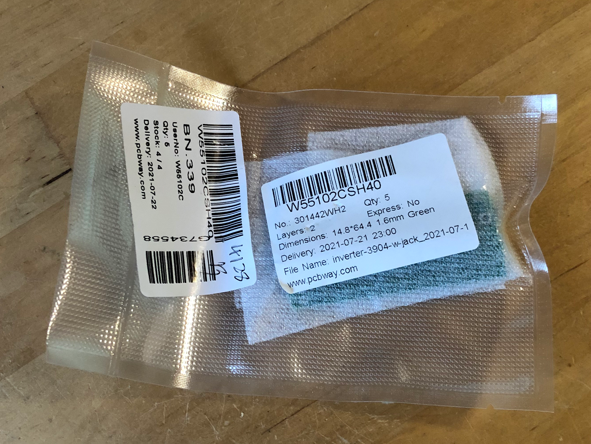
Next I hooked the MCU circuit to an inverter/buffer pcb I designed; I had the PCB fabbed fast by this Blog's new sponsor, PCBWAY. Thanks to PCBWAY for the help!

Here's the board packaged and ready to go, it arrived in the US 5 days after I ordered it.....go PCBWAY!
The PCB I had fabbed for this modification is a very simple single NPN transistor inverter:

 |
| Layout for the inverter/buffer |
 |
| Working gate inverter/buffer |
On a scope: output's high usually but we get a transistion to ground for each gate present at its input.
Let's Code! I wired the inverter to the dev board like this:
 |
| Simple! |
And used this code--its a single main.c file. This code works with the minimalist AVR 328 board posted here.
Now I'm ready to pull the DLFO out of the rack and try to add the interrupt code and inverter PCB/input jack'buffer to it. Note: older post about interrupt for the Arduino Sketch world is here.


No comments:
Post a Comment