Testing Embedded C Libraries--Who Cut the UART?

Highty Ho Boys and girls, more embedded C fun in the land of audioDiWhy. 

I'll be back with more hardware builds next month, but for now I continue to experiment with embedded C code for the Raspberry Pi RP2040 processor.

This week I ported an  AD9833 library I wrote for Atmel MPU's to RP2040. 

It's ready to test--however the new library has 25 methods and counting. How do I test the library without having to rewrite and recompile main.c over and over?  

I used UART.  This is the protocol that flowed between your 80's era PC clone and a <15K baud dial up modem. Useful things stick around; UART is simple, well documented, and supported in some manner on many computers and development boards.  

An informative webpage regarding how UART works is here.  


GET IT WIRED UP

RP2040/pico SDK makers can configure serial via USB configured through CMakeLists.txt but I found serial UART from my RP2040 developpment board simpler and more accurate once everything was set up correctly.

I am using a Raspberry Pi for sending and receiving UART serial communications from development boards. Setting a Raspberry Pi 4 up for serial wasn't as simple as I thought it'd be, but the video here helped. 

To wire it up:  

I created a 3 conductor wire with expando sleeving and dupont connectors for TX > RX, RX > TX, and GND < > GND. Note that you must connect ground between the host and the development board for any of this to work.

Assuming you are using my code: there are different UART pins on the Pico; you have to use the right ones. I used GPIO "0" or Pin 1 for RX; GPIO "1" or Pin 2 for TX, on the PICO. This conforms to defaults set in pico.h in the SDK.

On the RPi, I used GPIO pins 14 for TX and 15 for RX.  This is UART0.

On the RPi4, install minicom if it's not already there.  Settings are 115200 baud rate, and 8n1

To this end, make sure your CMakeLists.txt has "I want UART for serial, not USB" set correctly:

#control USB output--1 means on.

pico_enable_stdio_usb(${PROJECT_NAME} 0)

pico_enable_stdio_uart(${PROJECT_NAME} 1)

Wiring up the Pico for UART....


I use SSH to get to this Raspberry Pi SBC and then use Minicom as the terminal program


USAGE

UART and so on in the Pico API are documented here. This is a subsection of the PICO hardware API docs, here.

You can get the UART.c and UART.h files used in this post, ready to drop into your project, here. The basic use case for the library is documented in the library's UART.h.  

Here is basic syntax:

/*

put this in endless loop in main

READ_UART_BUFFER; 

// trap a matched string you type into your terminal program:

printf("%s\n",uart_buffer); // show what you just typed

    if (UART_READ("REBOOT"))// reboot right from minicom!!!!

        {

        reset_usb_boot(0,0);  reboot PICO

        } 

    else

        {

        // any other entry into the buffer does whatever is coded in              //here.

        }

    }

*/

AD-WHY? C WHAT? DEVWHAT? 

Why do any of this at all? (the audiodiWhy mantra....)

The AD9833 is a function generator chip--it has a reasonably wide frequency range (.1hz to 12.5Mhz), multiple waveforms, reasonably low noise, 2 registers for phase, sleep modes, and so on. I hoped to build a volt/octave FM synthesis board and other waveform generators using AD9833's along with  RP2040 development boards; for that I figure I need a working AD9833 library.

There are already Arduino libraries for the AD9833 IC (here), and I assume other popular microcontrollers, but maybe not for the RP2040. (Really? Not sure. I didn't en endlessly google RP2040 C AD9833 or whatever....so maybe a working PICO <> AD9833 C library was already out there? In any event, it wouldn't hurt to roll my own as a learning experience....)

A few mornings later the library was written and I was ready to test...so I started modifying main.c to test each method.

So:

tri(); 

after recompiling changed the waveform at output of the AD9833 to a triangle.  Works!  

Next in main.c I added

squarehalf(); 

and recompiled; this altered a square wave to .5* of the frequency found in either frequency register.  This worked as well.

phase1(1300); 

along with recompiling put a 14 bit phase value into the IC's phase 1 register.  That didn't work quite right so i tweaked it, recompiled, and after that yes, it worked.

You get the idea.


AD9833 Breakout Board

With all of these methods to test, modifying main.c, then re-compiling, then re-uploading to the Pico over and over became tedious.

How could this be streamlined?

For inspiration I didn't go out in nature--I didn't breathe the fumes--I didn't even talk to fellow geeks.  

Instead I turned to youtube. Specifically the video here. 

The content creator uses a UART serial stream to turn off and on LEDs on a Pico dev board, but as he mentions: there are other use cases. Testing libraries could be one of them.

So: I got this going on my bench. 

After configuring a Raspberry Pi 4 I had lying around, I wired the UART TX and RX to the RX and TX on the Pico following the steps at the beginning of this post.

Finally I SSH'd from my Ubuntu bench virtual machine to the Raspberry Pi, then once shelled in, ran minicom. Minicom of course can send data over serial by typing characters into its terminal, which I did to kick off each function under test.  

CODE ME UP ANNIE!

In a header file I called uart.h, at the top of the file, I declared a 1K global array, then wrote a global macro to compare a scanf statement to the contents of the newly created buffer. This almost straight out of  the aforementioned "low level learning" video, so again, if you've made it this far in today's post, you should consider watching it, the video is here.

// global buffer for uart reads

char uart_buffer[1024]; 

//define macro for endless loop in main

#define READ_UART_BUFFER scanf("%1024s",uart_buffer) 

//test to see if string X is in buffer. 

//Do whatever is in curlies {...} if there is a match

#define UART_READ(X) strcmp(uart_buffer, X)== 0

in main.c's main loop, I trapped a match between a string and what is in the uart_buffer.  

while (1 < 2) {

    READ_UART_BUFFER;

    if (UART_READ("TRI")) //gen tri wave

        {

            AD9833_Tri();

            CNTL_SEND; //macro to send via SPI the control uint16_t 

        }

AD9833_Tri() was supposed to change whatever waveform the AD9833 was generating to a triangle. Hooking the IC's output did the sine change to a triangle? Not at first, so I stopped and worked on the method--and no need to change main.c--and quickly had the function up running.

Next I expanded this paradigm so I could extract parameters from the serial data. UART only sends strings between systems, so, how could I trap numbers (decimals) to use as function parameters?  

For example, I wanted to test the AD9833's  FREQ0 register with 0x4000 0x4000.  Right after, I wanted to test 0x4000 0x5000.  

I could have written switch statements, or a lot of if ()'s in main.c.

Instead I created a new file, uart.c and wrote functions based on strncmp--on a match, the functions  extracted the ASCii style numbers; turned them to decimals and sent the uint32_t's to a function under test.  

Here's the code:

uint8_t compare_strings(char *a, char *b, uint8_t len)

{

   uint8_t x = 0;

   if ((strncmp(a,b,len))==0)

   {

     x = 1;

     return x;

   }   

   else

   {

      x = 0;

      return x;

   }

}

//////////////////

uint32_t dumpleft_conv2dec(char *hi, uint8_t chopleft, uint8_t digits)

 {   

    uint8_t i, len = 0;

    uint32_t result = 0;

    char *x = hi;  

    uint8_t count = 0; 

    count = chopleft;

    do

    {

          {        

        *(x + count - chopleft) = *(x + count);

          }

          count++;

    }

    while (*(x+count) != '\0');


    //deal with end of string 

   if (*(x + count) == '\0')

    {   


        *(x + count - chopleft) = '\0';         

    }


    //turn ASCII numbers into a decimel number

    for (i=0; i< digits; i++)

    {

      result = result * 10 + ( x[i] - '0' );

}

        return result;  

 }

compare_strings matches string array *a to *b from left to right, up to len characters.  If there is a match, it returns a 1. dumpleft_conv2dec then strips whatever characters I didn't want from the left side of the string (chopleft), and turned the rest of the string into a decimal value of length digits (keeping in mind that char "1234" did not directly translate to dec 1234--ASCii uses different codes for decimal characters!) 

 Now I can type FRQ02000 into minicom and main.c finds a match, gets rid of the "FRQ", and turns 02000 into decimal 2000.  

From here it's trivial to use this as a parameter to test a function:

 char f[4] = "FRQ"; // this has to be +1 greater than # of chars when creating array    

        if (compare_strings(uart_buffer,f,3)) // compare first 3 chars

        {

            uint32_t rez = 0;

            rez = dumpleft_conv2dec(uart_buffer, 3, 5);

            AD9833_LoadFreq0(rez);

           FREQSEND; //macro to send via SPI 4x freq bytes to register

        }


Ha! This worked! 

THE BIG LIMITATION

Putting a scanf() into the loop in your main.c means your loop will stop at the scanf(), waiting for input. This means your main.c loop won't loop. 

This worked for testing this library, but for other applications, say, reading a rotary encoder, probably not--you need your loop to loop! For that I can see using an interrupt and not scanf() when UART data comes in. 

I will probably experiment with modifying the code to use interrupts in an upcoming post.

ARDUINO AGAINO?

Another use for the UART paradigm is to run a high power processor on the back end and use something TX ready, like a Pro Micro, on the front end/user interface. The Ardunio handles the switches, pots, LEDs and OLED displays. 

As long as the end user can tolerate a brief delay--for example, a waveform that takes 100-200ms to change--an Arduino could send the same ASCII strings to the backend processor used during testing--we already know it works!

However, I have a faint recollection that RX and TX commuincation step on Arduino bootloaders--so you can't program an Uno R3 with the RX and TX pins connected to something sinking current.  Why do I think that? I don't remember, and maybe I'm wrong.  I hope I am. I guess we'll see.


Embedded C--Recursion, C Macros, Stupid Stack Tricks, and a Clever Hex to Binary Function

....if that blog post title doesn't make you want to watch paint dry then what will?

Working on an AD9833 library for RP2040? Maybe next post....getting there....


Onward!

I am always trying to sharpen my Embedded C skills, the programming language I primarily use to program MCUs.

This week I continue to work on an AD9833 SPI library (already written for Atmel 328--here), ported to work with 32bit MCUs like the RP2040. 

Today though I went down the rabbit hole, trying to find the simplest function for hex or decimel to binary conversion for printf()'s 

Why? Why not?

A lot of embedded C programming (and digital electronics in general) comes down to sending 1's and 0's from one component to another. 

Doh?

However at times I can visualize what 0b0001011001110111 is going to do when viewing the dataflow on a logic analyzer 

Something like 0x1677 doesn't fire up my neurons the same way. 

Is that just me? A lack of experience with hex? Maybe. 

Unfortunately, C has no easy means I know to printf() a binary number--hex, yes, decimel, yes, floats, yes, but binary, no. 

So, it's a matter of finding a hex to binary function I like online and stealing it? Sure. 

I found plenty of C hex to binary functions online that start with a string array and produce binary output as a string (for instance, here), but for what we embedded C folks work on (mostly numbers, not a lot of strings) that's not much help. 

I needed the input parameter to be a number, not an array.

After a bit more searching I found a brilliant little recursive function--original post is here.  

It's only 4 lines of code!

#include "hex2bin.h"

void hex2bin(int16_t h)

{

if (!h) return; 

hex2bin(h>>1);

printf("%d",h&1);  

return;

}

It works!!  

Orig number:  0xdc or 7618976
11011100
  

How does this wonderful fragment work?  At first I didn't care, don't look gift code in the mouth? 

But then it started to drive me crazy. I could see no logical reason why bin2hex() should not present its output in the wrong order!

Why did I think that?

once you run this

h  >> 1 

The number you're converting (say, x = 200) decreases down to 0, so you're done. 

But, if you don't recurse, the printf()'d output shows an incorrect binary value because it's backwards; for example, 0b1100111 is output when you wanted 0b1110011.  

However the 4 line fragment doesn't do this--somehow it prints the final result in the correct order.

But how, Scotty, how?

Sadly Cap'n Kirk's C skills were shit, but could he kick ass with Esperanto....


Turns out, it's a call stack trick--using Codeblocks, in debug mode, with the stack and watches debug windows visible (good tutorial for Codeblocks C debugging is here), it was easy to see what was happening.

I created a simple (and very similar) function that subtracts 20 from "h" which in this case is 220:

void hex2bin(int16_t h)

{
printf("h is: %d \n",h);
if (!h)
{   printf("IN RETURN. H is %d \n",h);
    return;}
else
{
    printf("not there yet \n");
}
hex2bin(h - 20);
printf("h is: %d \n",h);

}

The stack looks like this--the call stack loads its data "upwards"--so the values of h - 20 appear in reverse order:


Here is the output from the hex2bin function, called from main.c, with a parameter value of 220:

0bh is: 220
not there yet
h is: 200
not there yet
h is: 180
not there yet
h is: 160
not there yet
h is: 140
not there yet
h is: 120
not there yet
h is: 100
not there yet
h is: 80
not there yet
h is: 60
not there yet
h is: 40
not there yet
h is: 20
not there yet
h is: 0
IN RETURN. H is 0
h is: 20
h is: 40
h is: 60
h is: 80
h is: 100
h is: 120
h is: 140
h is: 160
h is: 180
h is: 200
h is: 220

The trick: when the code runs the printf() over and over, printf() starts at the top of the stack and pops the data off from top to bottom--from 20 to 220--which is the same behavior as hex2bin(), giving us exactly what we need.

Stupid stack tricks!  It works!! Genius!!!

Experimenting with this I found that any intelligently written recursive algorithm that stopped when a true was reached, with return statements in the right spots, would load the stack in the same manner and thus allow the function to return data backwards. I figure other use cases are possible--for instance, load an array in reverse order. I will experiment with this....in the meantime, it shows how to really master C, you have to know how the underlying hardware works.


Not done yet! this is a recursive function, so, how could I put a 0b in front of the 010111, and an \n at the end, and any other window dressing needed? 

Since the 4 lines recurse, I couldn't put more printf() statements elsewhere in the function--I ended up with a whole bunch of 0b's at stdout each time the function recursed--something like

0b00b10b00b10b10b1

Yuck!

I ended up using a macro with a parameter in the .h file--another stupid C trick I didn't know about; but now I'm playing with power.

#include <stdint.h>
#include <stdio.h>

#ifndef HEX2BIN_H_INCLUDED
#define HEX2BIN_H_INCLUDED

//here's the macro....watch the line wrap....
#define HEX2BIN(X) printf("Orig number:  0x%x or %d \n",X);printf("0b");hex2bin(X);printf("\n")
 

void hex2bin(int16_t h); // c


#endif // HEX2BIN_H_INCLUDED

the #define prints a 0b in front of the conversion, and a carriage return at the end. Took me a bit to get the syntax right, but now, I know it.

Then I could call the macro from main.c arguing in a value of 220:

#include <stdio.h>
#include <stdlib.h>
#include "hex2bin.h"

int main()
{
    HEX2BIN(220);
    return 0;
}

Yeh baby!  Seems working!!!!  Get bin2hex C code from Github here. 

OK enough C for a Sunday. I worked most of the day digging into this. Did I get outside the house much? Nope.

 A very fine day it was. 

EuroRack Easy Mult and Getting Front Panels Fabricated--Cheap!

 I said last time I'm taking a break from digital, what's easier than a passive mult for a Eurorack Synthesizer?


You can buy these online, but making your own is easy and inexpensive. Get the gerber, schems, etc from my wonderful sponsor, PCBWAY's, project page, here.

USING THE MULT: The top 3 jacks and bottom 2 are wired together, but if you insert a plug into the 4th jack down, it becomes a 3x3. 


As per the post here, PCB material can make great front panels, but sometimes it's hard for the fabricator to know if you want a front panel or if you just forget to include traces in your gerber (!).  

I get around this by putting a small SMD pad on the front:


.....as well as a few fake parts--usually pads for SMB resistors--on the back, along with some fake/meaningless silkscreen legends.  

This usually gets fabricators to put their job number on the side that users don't see; in my experience their job number gets added to the "busier" side of a two sided board--so put a few fake SMD and traces on the back of the front panel.  

Finally, equest that your front panel be done up in black....


As usual, thanks to PCBWAY for sponsoring this blog and keeping it all going.

Now, your front panel goes through the fabricator's algorithm. Before long you have a ready to use front panel.

(quick post, thank goodness.....) 

Again, the link to the Eagle files and gerbers--the PCBWAY project page--is here. I include 2 front panel variations, one has a center drill for your Eurorack screws, the other has a milled oval. So look for 3 gerbers on the project page. The front panel that has two milled ovals for rack screws will be a bit more expensive to fabricate but will give you more options as far as where you can rack mount it. You may want to change the location/size of the top and bottom drills, or change the milled oval, but for what I do, the less expensive to fabricate, simple drilled version worked fine.

RP2040--I2C Library for Embedded C--The Run Screaming Post

Welcome back to the land of lost readers!  If you are an embedded systems ("IOT") hobbiest, the embedded C discussed in this post will probably make you run screaming; there are higher level languages like Arduino Sketch and MicroPython that, for robotics, audio, getting Rover to use her litterbox, making sure your garage door is shut, etc., "just work"----and are far easier to code. 

If you're an electrical engineering professional and you need added speed from compiled C--you probably know C, inside and out, already, much better than I do; you have been coding C for years?  

I'm in the middle, with unfortunate occasional regressions towards newbie; interpreted languages were too slow for my projects and at times learning Arduino C abstractions was taking longer than coding using a lower level language. 

I like a challenge; C can be that for sure. 

Soooo....hello C.....frustrating, puzzling, and wonderful. 

If you're still with me, read on.....  


THE CHALLENGE

I am transitioning from Atmel 328P embedded C (used in Arduino development boards such as the Uno R3) to the RP2040, an ARM dual core M0+ based MCU from the Raspberry Pi Foundation. 

Porting code from Atmel to RP has been--challenging--since these processors are fairly dissimilar. 

I have already set up a toolchain (here), built an inexpensive step debugger (here), and coded libraries for the 2040's built in ADC's (here), SPI abstractions (here) and this time: a library for the I2C protocol.  


AD4728 cheap I2C breakout board

I2C WRITE

The RP2040 API has several I2C functions already good to go (here), but what fun would it be just using that?  

To better understand how the RP2040 hardware I2C API works, I wrote my own I2C library abstractions using their I2C abstractions.  

(Have you run screaming yet? No? Congratulations, you have passed the Frank Zappa test. Let's keep moving forward.....)

The challenge: could I get an MCP4728 quad I2C DAC breakout board ("BoB") to produce analog voltages I can see on an oscilloscope. 

I had this working for the Amtel 328 (get that library here)--one of my first embedded C coding experiences, and yes that's some crap code!; the MCP4728 IC does a lot but my library for it is stripped down; it provides only a method to send 4 simultaneous values to the ICs four DACs and not a lot more.

If I could get that to work with an RP2040 that'd be good enough, I figured. 

Porting existing MCP4728 Atmel C code took a few hours...not too bad. 

The SDK for RP2040 mandates that write values be send to a buffer (in other words, the values for your DAC write must be written to memory).  For that, I crafted an 8 byte array in main.c.

Then I passed this array to other functions--necessary to get the C code to work in any form. This was not as hard to code as it was when I first started on my Pure C adventure (initial post is here; I feel I've come a long way--if you're ditching python or sketch for C and C++--stick with it--it gets easier as you go.)

//write I2C bytes then stop

//arguments:

//*i2c    i2c0 or i2c1

//addr    address of I2C chip 

//*src    pointer to buffer that has the data you want to write

//nbytes  number of data to write, not including address

uint16_t I2C_Write_nbytes_stop(i2c_inst_t *i2c, const uint addr, const uint8_t *src, const uint8_t nbytes);POINTER ALERT!

AN ASIDE IN ITALICS

Pointer warning for anyone getting started with C: Yeh, they suck. Easy for a pro. Hard for a beginner.  Attention youtube super duper content creators: "pointers are simple". Baloney! To play a flute, blow here, and move your fingers here. Sounds great! My 2 cents: pointers are like so many other things in life: How do you get to Carnegie Hall?  Practice, practice, practice. 

And! For anyone wondering why you need pointers in C at all: for one, the RP2040 SDK requires you to write your code this way--otherwise you get nothing! 

So roll up your sleeves....


MCP4728 under test...

I2C READ

After seeing 4 stupid voltages on my scope it was time to move on to an I2C read. 

 I haven't done a lot with I2C for injesting data; built-in MCU ADC or SPI ICs tend to be simpler to code so that's what I've used to date.

Nevertheless I wanted to make sure I2C read functions in the library worked. I bought (for USD $1.50 each) a few PCF8591 breadboards from tayda to test the code.

It's a quad 8 bit ADC, see the datasheet here. These BoBs do a lot--differential inputs, a DAC output, etc. Opting for simplicity--I wanted to see if I could read a single channel value into the MCU then output it via UART to a Raspberry Pi 4 SBC--good enough.  

Main problems: the chip's address is 0x48 and the read/write bit is ignored (it's in the datasheet, but I missed it) and from trial and error and looking at data with a logic analyzer it seemed (?) to get a good read from the PCF8591 you have to read in a byte of data, ignore it, then get the next byte...I knew that..... 

Once it was on the bench I used Pulseview to analyze the logic:

I am realizing a logic analyzer is as important to digital electronics as a scope is to analog. A good place to start is Sigrok.

Simple issue--I had the address wrong--0x90, oops, not 0x48--easily spotted and fixed.  

For logic analysis, I am using an $8 saleae clone--but the Windows 10 driver keeps quitting on it, and the application crashes from time to time. I am debating laying out big money (>$1K USD!) for a non-clone....yes a real Saleae analyzer--what's my time worth?  Update: I bit the big one and bought a $1500 Saleae Pro 16.  Not a clone! Who needs to pay for food--put it on the credit card! A lot of money, but, I figure it's probably the last logic analyzer I'll ever need to buy).

PCF8591 Quad 8 bit ADC on a BoB. $1.50USD each--incredible value
!!!

"Seems working". 

If you want to take a look at the library (congrats for hanging in there) it's on github--here. 

With all of this in mind, I am beginning to hone in on a personal, organizational standard for ongoing embedded C projects:

  • Each IC that needs code (ADC chips, DAC chips etc) gets its own .c and .h files. This is for portability/reuse in other projects.
  • Any global variables needed for an IC, such as a structure to set and change bits for the IC's registers, or an array to hold the summed output of the structure's content, and so on, is declared as a global variable in the .h file associated with the IC (so, in MCP4728.h, AD1115.h, etc). These need to be declared as static, extern, and so on, as needed. I read in places this is not a C best practice. But then I see a lot of .h files and main.c's that use this convention. Sorry.
  • Structures for ICs and buffers used to ultimately communicate information to SPI, I2C etc., should be reachable via a pointer instead of the other ways to do it, when possible.
  • Limit the amount of function returns when it makes sense--again, modify memory with a pointer.
  • The methods to communicate with ICs (SPI, I2C) are in their own libraries; not in the IC libraries themselves.

I'll see if I can make this work in upcoming projects....

Enough coding for now! I had plans for my next real digital project--some sort of gee whiz VCO thing with an RP2040--but right now I'm kinda sick of it, so I might lay out some analog boards just for fun. 

Fun--that's the idea right?

Otter Mods "GateKeeper"--Trigger to Gate Euro Module

Hello again. I am still working away on a RP2040 toolchain--stuck on getting I2C to work--so I've turned the post over this time to Elton Glover from Otter Mods--they make really cool analog synth modules, and Elton was nice enough to share one of his designs--"GateKeeper" with me and you, faithful AudioDiWhy readers. 

Take it away Elton!

=====================


The Timer

The core of this module uses a 555 timer to generate a gate of a desired length. If you are not familiar with this versatile chip, there are many tutorials available online. Here is a link to a tutorial and a calculator to help determine component values:


555 Calculator

https://ohmslawcalculator.com/555-monostable-calculator


555 Tutorial

https://www.electronics-tutorials.ws/waveforms/555_timer.html


Configuration

The 555 timer is set up in monostable mode, often referred to as “one-shot” meaning it will not self-oscillate. With the values I chose, the adjustable output gate can range anywhere from ~0.02 seconds up to around 5 seconds. Some of the resistor and capacitor values (specifically RV2 and C3) can be adjusted for longer or shorter duration, but I felt these gave me a good usable range for the typical patches I’m making.


This version of the module build uses through-hole components for easier assembly, but I have also made a double gatekeeper version using SMD components. You can tune the build to your own taste.


Functional Walkthrough

The clock input (J1) can accept nearly any type of signal pulse, which is then fed through the filter made up of C1-R6 and passed through D1 to produce a spike. This is buffered by U1A and the output turns on Q1, which is set up as an inverter.


This inverted pulse is fed into the Trigger (pin 2) of our 555 (U2). This initiates the charging cycle of C3. The combination of R5 with the adjustable value of RV1 sets how long this charge time takes. Once the charge level of C3 reaches the ⅔ supply threshold, the Discharge (pin 7) is opened and drains C3 until another Trigger event occurs. Concurrently, the Output (Q in this schematic, pin 3) turns on during the charge time of C3. The output is buffered by U1B and is the end result used to output the desired Gate signal. R1 and D2 provide an indicator LED to signify the gate output length. R2 is used as a simple means of circuit protection.


PCB Layout

Here is how I chose to layout the board. I am using the 3.5mm jacks as the mount for the faceplate, and thus wanted to space them out evenly across the board to give the module the most support. 


This module is 3HP wide, and the standard 3U height for the Eurorack format:


You can get your own Gatekeeper PCB and its front panel on PCBWay's project page, here.

=============

COOL!  Thanks again to Elton Glover for letting me post this extremely useful module. Also for PCBWAY for fabbing the PCB's for the post (there are two--main board and PCB used for the front panel). Get gerbers for both here.  

If you have questions or need more information, please contact Elton via his website--here.

I'll be back soon with more Euro modules, and maybe someday I'll have an RP2040 MCU working well enough on the bench to do useful things. Stay tuned!

RP2040--SPI "Wrapper" Library for Embedded C

This time I continue working with Raspberry Pi Foundation's RP2040 MCU for future in audio projects.  

Over the last few mornings I created a embedded C library for using SPI peripherals for this MCU.  


Breadboard time....

I couldn't locate many videos about programming RP2040 SPI using C; one I found covered both MicroPython and C. It's from Shawn Hymel--this guy has good stuff--video here. Also, the YouTube channel "Life with David" has some good RP2040 content (such as an interesting arbitrary waveform generator video how to--here) but so far not a lot about SPI; David concentrates on the RP2040's PIO features, primarily.

Using those videos, as well as the (surprisingly abstract) examples found here, and the SDK SPI documentation from Raspberry Pi Foundation, I ported/rewrote the Atmel 328 SPI library I create a few years ago (here) to code for the RP2040.  If you are new to SPI and embedded C, you should read up on SPI first--good article from the Sparkfun folks: here. 

After a few mornings, I got it to work.  

Proof of concept--1K triangle wave created with the library discussed in this post and an MCP4921 SPI DAC. Code is here.

There are differences aplenty between Atmel 328 and RP2040 hardware and firmware. For example, the RP2040 supports 16 bit SPI communication; as far as I know, the Atmel 328 natively only supports 8 bits. The RP2040 has 2 SPI peripherals on-chip, the 328P has one. 

Pulseview is open source logic analysis software; I used it with an inexpensive Saleae clone to see what was happening with SPI at a low level. A logic analyzer is essential for debugging libraries like this one.

One of the main differences I found is that the RP2040 requires buffers for SPI data being sent and returned; this is required by the Pico SDK. 

This was easily accommodated; I created a suitably sized variable or array, then, when calling a SPI write method from the SDK, I used the address of the buffer to pass the data to the peripheral:

void  SPI_TransferTx16_SingleCS(spi_inst_t *spi, const uint16_t data) // cs low, 2 bytes, cs high)

 {   

  gpio_put (cs_pin,0);   

          spi_write16_blocking(spi,&data, 1);  

  gpio_put (cs_pin,1);

 }


The number 1 you see above indicates how many words occur between the CS down and CS up; so it was  easy to create another function where you can argue in as many bytes as needed:

void SPI_TransferTx8_variable_num_words(spi_inst_t *spi, const uint8_t a[0], uint8_t numwords) 

// 8bit write, cs down; variable # of bytes before CSup 

{

    gpio_put (cs_pin,0);   

  spi_write_blocking(spi,a, numwords);

          gpio_put (cs_pin,1);

 }


I already had a single method MCP4921.c file I've used for Atmel 328/embedded C (here), but since the RP2040 can accommodate 16 bit words for SPI, I simplified the code for the MCP4921 DAC 12 bit writes to just three lines:

void write4921(uint16_t data4921)

    {

     // code assumes LDAC (4921 pin 5) tied to ground

     data4921 &= ~(1 << 15); // must always be zero 

     // buffered ref in, gain = ref; no shutdown

     data4921 |= (1 << 14) | (1 << 13) | (1 << 12) ;  

     SPI_TransferTx16_SingleCS(spi0,data4921);    

    }


To test and troubleshoot, I used PulseView, the amazing and extremely useful open source logic analyzer. Using Pulseview I could quickly see if a given library call worked or not:

I tested sending hex FF, F0, and 03 (so 24 bits) between a single CS down and up.  Yes, it worked. However, SPI tests don't reveal useful information without an appropriate peripheral connected to the MCU. So, I tested this write method using an AD5761, which requires 24 bit words for each SPI transmission.

I posted the initial build of the RP2040 SPI library "wrapper" on github, here. I am calling this a wrapper because RP2040's C SDK already has functions for SPI, but I wrapped them up into something more along the lines of how my mind works. 

I didn't have any suitable SPI chips for reads/MISO, so, as of the writing of this post, I am guessing at those functions. I have ordered a few MCP3001/3002 IC's (SPI ADC). I will test with that in a week and update the post and/or the library once I am sure those functions are debugged.  Update: reads work!


I got the MCP3201's on my bench and yep, the functions for MISO/ADC read worked first time.  You ca n see the wiring I used for the ADC chip; I added MCP3201.c and .h files to the github SPI repository. 

One more tidbit: VSCODE, the IDE I chose for this RP2040 toolchain, supports a Microsoft technology called Intellisense. 

Among other things, Intellisense allows the user to hover over a method and see details about its use. 

OK how did I add Intellsense detail to the 2040 SPI C library?  It's easy: in my declarations (specifically: SPI_rp2040.h) I commented immediately above where I defined the function. But I added no comments on the same line as the declaration: 


These comments appeared via Intellisense when I hovered over a function in Visual Studio Code:


Next, onward to an ADC C library for RP2040.  The RP2040 has 3 12 bit ADC's, a built in temperature sensors, and some interesting features like ADC round robin. Update: done, here. 

In general, in the coming weeks and months, I will probably port more Atmel 328 libraries I have already written to this new MCU, and try to improve and optimize the code in the process.  Geek out, baby!


RPPICO/RP2040 Toolchain Part II: Debugging RP2040 projects using a "PicoProbe" and Ubuntu 20.04

This time I continue to set up a toolchain for the RP2040 for Ubuntu Linux 20.04 running as a virtual machine.  To follow along, you'll first need to set up the basics--or at least skim the last post--here.

Hello again! There are about 8 billion people in the world; am I the only one who wants to set up a debugger for the RP2040 MCU--what the Raspberry Pi Foundation calls "PicoProbe"--centered around an Ubuntu 20.04 LTS virtual machine?

And code in C, not MicroPython?

Um....Perhaps?

Picture this: a debugger interface as big as a box of matches. Works from Linux command line as well as VSCODE. We can put the incredible horsepower of GDB--a well known open source C/C++ debugger--to debug an ARM MCU....the RP2040....all for $4USD?....unbelievable!!!! 

If I can get it to work.

WTPP (or) Rasberry Pi in yo Face

PicoProbe uses an intermediate Raspberry Pi PICO dev board to provide SWD debugging to our target RP2040; we also need a computer to run GDB.  

It's not simple.  

I found generic Linux debugger toolchain installation steps from Raspberry Pi and elsewhere, but quickly discovered they didn't apply and/or were out of date for Ubuntu Linux 20.04.  And, almost every Linux based build I found used a Raspberry Pi SBC as the host Debian based PC, e.g., here, as opposed to an Ubuntu virtual machine.

Sure I could set the step debugger up on a Raspberry Pi SBC, but they are very hard to buy right now, being out of stock everywhere. And to paraphrase the great John F. Kennedy: we do [Embedded C toolchain setups on Ubuntu] not because they are easy, but because they are hard.  

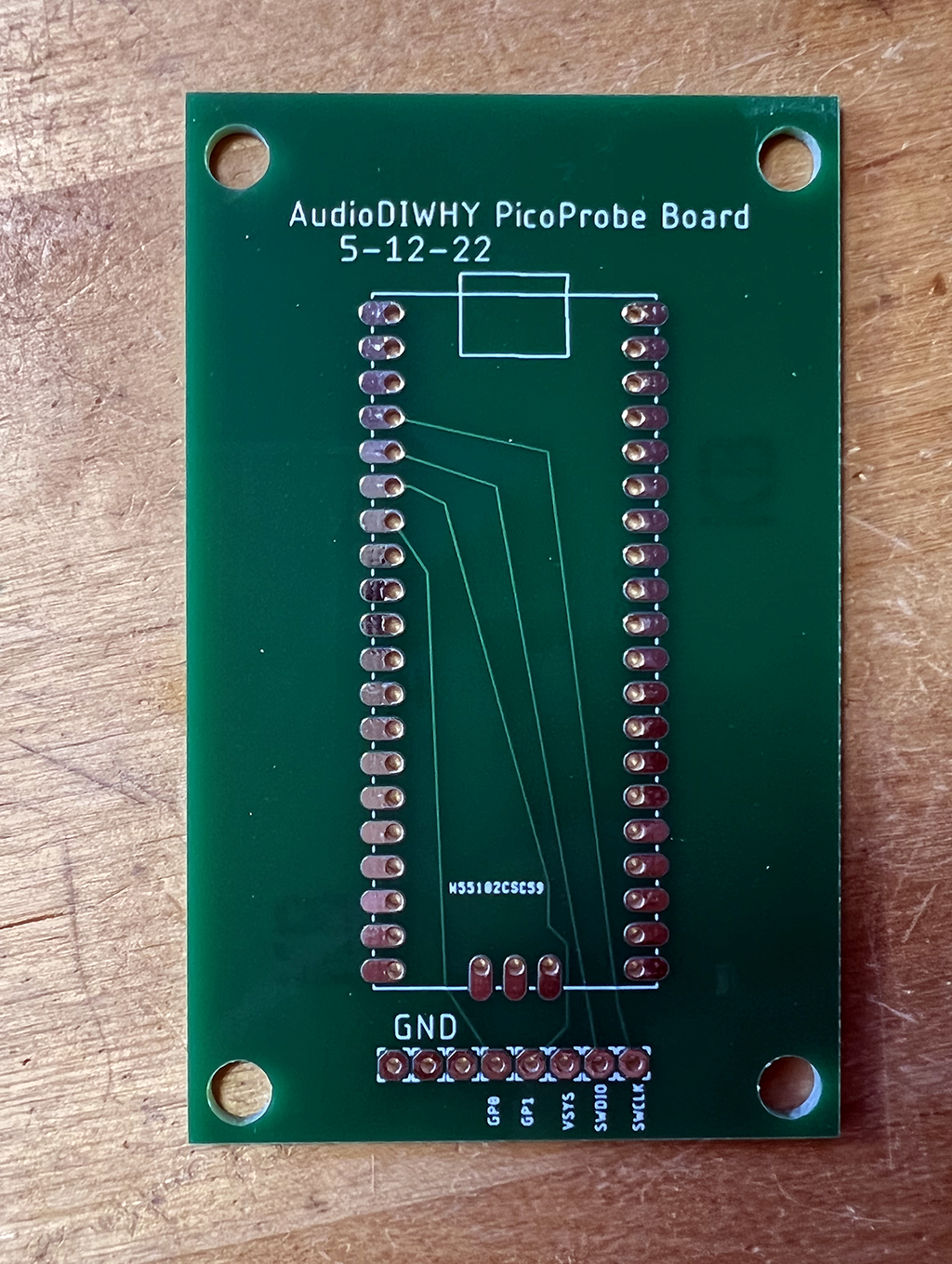
I created a simple PCB to simplify patching between a PicoProbe SWD Debugger (left) and the RP2040 Pico target (right). I'll go over this PCB in this post.

Let's go!! 

I found two thorough videos for setting up a PicoProbe toolchain on Windows: here and here, and a good document outlining the same idea here. 

To understand how the toolchain (PC > PICO running a "PicoProbe UF2 > target RP2040) works, please watch the beginning (at least) of the excellent video from Shawn Hymel, here.  I am not going to outline each piece of the computer > Picoprobe > PICO debug toolchain puzzle in this post, because Shawn does an great job explaining them in his video. 

Me? I followed the RPI PICO Getting Started Document, page 58, and installed these packages on the Ubuntu 20.04 VM:

#sudo apt install automake autoconf build-essential texinfo libtool libftdi-dev libusb-1.0-0-dev

Next I followed the instructions on page 57 of Getting Started to set up a special pico version of OpenOCD, the service that allows the GDB debugger to talk to the Pico.

#git clone https://github.com/raspberrypi/openocd.git --branch picoprobe --depth=1 --no-single-branch

#cd openocd

#./bootstrap

#./configure --enable-picoprobe 

#make -j4

Here I found my first serious bump.  OpenOCD wouldn't compile--error 2 during the make command. The error was an indent bug (?) deep in the guts of the downloaded openocd.git code. 

No way I had time to rewrite the customized openocd source code so it'd compile on Ubuntu, that would have taken forever. Crap!  

After digging into the branches of the github repo, I guessed that the git clone command provided by RPi was out of date; I figured the repo changed and the official documentation didn't keep up. 

With fingers crossed I issued this command:

#make clean

then this:

git clone https://github.com/raspberrypi/openocd.git

cd openocd

./bootstrap

./configure --enable-picoprobe 

make -j4

sudo make install

Ha! It compiled!  I was right I think; the repo had been updated, but not the documentation. Time wasted: maybe 45 minutes.

Next I created a UF2 file for the Picoprobe.  This was straightforward, I used the toolchain I set up in last time and ran this:

(cd to your projects folder)

#git clone https://github.com/raspberrypi/picoprobe.git

#mkdir build

#cd build

#cmake ..

#make

No issues here. 

I uploaded the PicoProbe UF2 file to the Raspberry Pi Pico dev board I was going to use as the "go between". You can see how to do that here: 

"hold down the BOOTSEL button while plugging the board into USB. The uf2 file below should then be copied to the USB mass storage device that appears."

PICOPROBE PCB

I could have wired up this second PICO running the PicoProbe UF2 on another breadboard, but instead I got help from my faithful sponsors, designed a super simple PCB, and uploaded it to PCBWAY for quick fabrication. 

Back it came:

Boards arrived super fast from my generous sponsors PCBWAY.  Please help out a blogger (me) who is trying to teach himself electrical engineering in his spare time and check 'em out.


 I put edge connectors into a Pico Dev board and soldered it to the PCB:


bottom view....


Next I wired the new Pico Probe PCB (left) to the blink board from last time using dupont type M/M cables:

(The board on the right is running the Boring Blink Sketch from last time.....)


For wiring I matched the females on the probe board (left) to a Pico dev board (right).  The PCB has the names of the pins to connect to the target--so, wire SWCLK legend on the PicoProbe PCB to the SWCLK Pin on the target breadboard, the GP0 pin on the PicoProbe PCB to GP0 on the target, and so on.  

The LED on the PICO board went solid--and the target BLINKCL PICO still binked--still alive! The PCB worked. I put the PicoProbe PCB on PCBWAY's projects page; if you want to get one, go here.

Next I needed to get OpenOCD configured. In this use case, OpenOCD allows the computer to "talk to" GDB.

But did openOCD start up? Not at first. I started up a new terminal on my Ubuntu system, but the bash  code on page 60 of getting started didn't start openOCD on Ubuntu correctly and kept throwing errors. 

Fiddlesticks!!!!

After messing around with different command line variations, I eventually go this to work:

#sudo ./openocd -s ../tcl  -f ../tcl/interface/picoprobe.cfg -f target/rp2040.cfg 

And could see this from the Ubuntu terminal:

Open On-Chip Debugger 0.11.0-g610f137d2 (2022-05-28-16:27)

Licensed under GNU GPL v2

For bug reports, read

http://openocd.org/doc/doxygen/bugs.html

Info : only one transport option; autoselect 'swd'

adapter speed: 5000 kHz

Info : Hardware thread awareness created

Info : Hardware thread awareness created

Info : RP2040 Flash Bank Command

Info : Listening on port 6666 for tcl connections

Info : Listening on port 4444 for telnet connections

Info : clock speed 5000 kHz

Info : SWD DPIDR 0x0bc12477

Info : SWD DLPIDR 0x00000001

Info : SWD DPIDR 0x0bc12477

Info : SWD DLPIDR 0x10000001

Info : rp2040.core0: hardware has 4 breakpoints, 2 watchpoints

Info : rp2040.core1: hardware has 4 breakpoints, 2 watchpoints

Info : starting gdb server for rp2040.core0 on 3333

Info : Listening on port 3333 for gdb connections

So--what was in the Linux docs section from the official documentation didn't work on Ubuntu and had to be slightly modified. What do you want for free?  Time wasted: about 20 minutes.

Next I had to get GDB going in a second terminal. That should have been easy, but there was a (big) hitch--this wasn't Linux GDB I needed; rather, a special version of GDB for ARM processors, and arm gbd does not come with the gcc-arm-none-eabi package for Ubuntu. 

A baby's ARM, holding an apple? 

Damn! 

After doing some research, I found the stack exchange post here, which I used to solve the problem:

Install lib n' curses:
#sudo apt install libncurses5

Then, from a browser, I went to this URL and downloaded the x86/64 version of the ARM dev tools: 


Next I created a brand spanking new directory for the GDB executable:

#cd /usr
#sudo mkdir gdb  #creating new folder: /usr/gdb

I figured all I needed was GDB, the rest of the arm-none-eabi already worked, and assumed (!!) this newer ARM GDB version could coexist with the arm-none-eabi-gcc compiler I was already using, as long as the compiler was older than GDB.

This was a guess, but I had observed GDB used for other non-embedded projects to be pretty forgiving....

I unpacked all the gcc-arm-none-eabi files into the new directory:

#sudo tar xjf ~/Downloads/gcc-arm-none-eabi-10.3-2021.10-x86_64-linux.tar.bz2 -C /usr/gdb

Finally I simlink'd gdb, to fool the RP tools to thinking it was in /usr/bin:

#sudo ln -s /usr/gdb/gcc-arm-none-eabi-10.3-2021.10/bin/arm-none-eabi-gdb /usr/bin/arm-none-eabi-gdb

Did I have all the tools we need?  I ran the next four commands--yes--I didn't record the results, but the tools I needed were now in place.

arm-none-eabi-gcc --version

arm-none-eabi-g++ --version

arm-none-eabi-gdb --version

arm-none-eabi-size --version

Next I ran gdb (finally!) vs. the BLINKCL elf file from last time:

#arm-none-eabi-gdb BLINKCL.elf  

and got this at stdout: 

target remote localhost:3333

(gdb)

OMG!  The beloved (gdb) prompt!  Was this going to work????

(gdb) load   

 rp2040 running BLINKCL stopped blinking

(gdb) monitor reset init

(gdb) continue 

the rp2040 started blinking!!!

and we see the (gdp) prompt again!  

It worked!!!!  I could now use command line gdb to debug, same as if I was debugging C code on Linux!!!

BONG HIT VICTORY!

But wait--we're not done! 

Could I get debugging to work without leaving VSCODE? The video here and accompanying webpage here made this look--doable.

I followed this Shawn Hymel webpage and followed the section on installing the Cortex Debug plugin on.  It all seemed to be OK, including coding the settings.json and launch.json scripts.

However, when i tried to use Cortex/VSCODE to debug the blink elf file I got this:


Great, there was some sort of log to review, but where was this gdb-server's output?  

I wasted at least two hours throwing every bit of GDB kung fu I knew at this....do we enable logging?  Does log.txt show up somewhere? 

It should right?  However, there was frighteningly little information I could find online. Again, there are 8 billion of us, but I may very well be the only person trying to set up this exact version of the toolchain. Damn.

After many frustrating hours on this, I decided to watch videos about STM32 VSCODE toolchains, since I remembered that some of them used the same VSCODE Cortex Debug plug in. There was zilch about RP2040 and this error, but maybe it occurs for other MCUs?

Bingo! That did the trick, STM32's VSCODE toolchains indeed can throw the same error, and I saw a video that revealed the output for GDB was in VSCODE's terminal--click on the TERMINAL tab then on the right, the gdb-server link--my lord, how did I miss this???


From here--now that I could read the logs--it was obvious that it was a Linux rights issue for the USB port for the PicoProbe. 

I had seen this issue before; to fix it I ran this from the Ubuntu VM:

#sudo lsusb

Which showed me:

Bus 002 Device 005: ID 2e8a:0004 Raspberry Pi Picoprobe

I chmod'd that....

sudo chmod 666 /dev/bus/002/005

 After, the VSCODE debugger worked! Time wasted--oh, never mind.

BONG HIT VICTORY--MACH II! it's done!  I can next/step/continue/print etc. with VSCODE. 

That was fun--man, much harder and more time consuming that I expected. 

But: for $4, for this amazing code and functionality, that developers, RPi, etc. etc., must have put hundreds or thousands of hours into, well, I can't complain, so I won't.....but, this setup kinda sucked.

Here's the final vscode launch.json that worked for the picoprobe.

{
    "version": "0.2.0",
    "configurations": [
        {
            "name": "Pico Debug",
            "cwd": "${workspaceRoot}",
            "executable": "${command:cmake.launchTargetPath}",
            "request": "launch",
            "type": "cortex-debug",
            "servertype": "openocd",
            // This may need to be arm-none-eabi-gdb depending on your system
            "gdbPath" : "gdbroot",
            "device": "RP2040",
            "showDevDebugOutput": true,
            "configFiles": [
                "interface/picoprobe.cfg",
                "target/rp2040.cfg"
            ],
            "svdFile": "/home/clamm/pico/pico-sdk/src/rp2040/hardware_regs/rp2040.svd",
            "runToMain": true,
            // Work around for stopping at main on restart
            "postRestartCommands": [
                "break main",
                "continue"
            ],
            "searchDir": ["/home/clamm/pico/openocd/tcl"]
        }
    ]
}

USING THE DEBUGGER

There are lots of videos about using gdb to debug C. (here for instance--"Low Level Learning" has a lot of great content).  

Lots of posts too; use the usual web searches. 

There are less videos about debugging using Cortex/VSCODE for RP2040, but there are several for using it to debug STM32's (e.g., here).  

And remember: after a debug, you still have to copy your repaired/modified UF2 file to the dev board--the debugger won't do that for you.

As usual: I'm not completely done, I'd still like to get a disassembler working, and I found some promising python code online, but I need to experiment with it further....one of these days. Until then, don't debug the fumes.