Arp 2600 Synth Preamp Workalike--get a 10x-100x-1000x Boost!!

Hats off to this blog's sponsor, PCBWAY....check out their Community Page--clicking those links lets 'em know I have readers, which helps me create new projects. Thanks!

==========

This time I continue to clone or knock off subcircuits from the legendary ARP 2600 synthesizer.  From my patient sponsor PCBWAY I recently received an ARP 2600 inspired synthesizer preamp PCB I laid out.  Let's see if my design works or is butt.

But first, here's an incredible (?) piece of luck....I was walking around my neighborhood the other day and in a sidewalk box bursting with "Covid Pandemic--Free Stuff!" found an almost new-in-box Radioshack/Realistic dynamic microphone circa 1970 or so:

USD $9.95! Hi-Fi Response! 10K impedance!

The box was a bit worn but the mic inside seemed to be good as new....being period correct and all, I will use that to test my preamp. 

The mic terminates in a 1/4" plug; I used a 3.5mm cable adapter. Can't beat FREE. 

ARP's design is a single op amp stage with a 3 way switch to select x10, x100 or x1000 boost by choosing different resistors in its negative feedback loop.  


I know (knew?) zilch about mic preamp design but digging around the Internet: using op amps for the gain stages was an easy way to go.

I figured the hardest thing was finding a "Range" 3 or 4 position toggle switch I liked. After a bit of thought I decided to have each output signal (x10, x100, x1000) have its own 3.5mm jack instead of using a switch. This took up more space but was simpler to lay out. 

I also decided to provide a cap-coupled AC input and a DC input; the ARP is capacitor coupled only. The DC input would be normaled to break the connection to the AC input if used.

Furthermore, I brought a x1 output to patch to use as a unity gain buffer. 

You can get the original schematic for the ARP preamp here (go to page 11). It's a pretty simple single op amp design; ARP used a Teledyne 133901 op amp with some clever resistor switching to get different output levels. 

I took a different (and I think, simpler) approach to ARP's; I used 4 op amp stages in series:
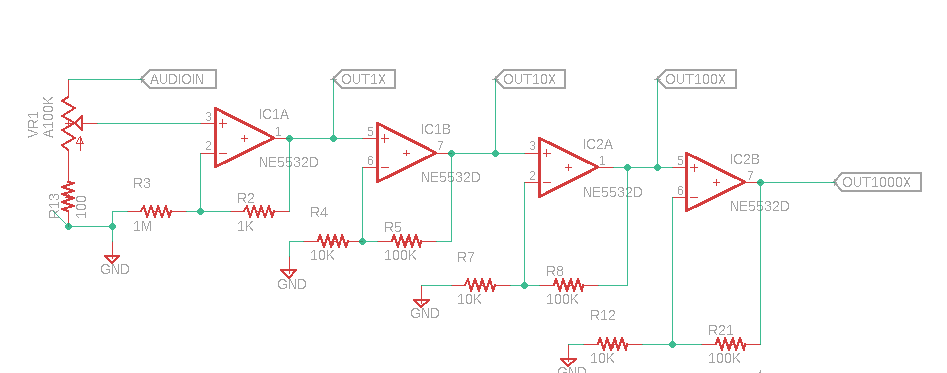
The rest is power and jacks...."keep it simple, stupid."

New boards from PCBWAY....


SOIC op amps were used to save space....


Ready to test....

I found .1uF filter caps for the op amps to be necessary to get rid of a bad buzz at the x100 and x1000 gain outputs.

When I first powered up the board it acted strange--the 10x output seemed too "hot" and the 100x and 1000x outputs were slammed against V--.  

After looking at this for a bit I realized I used the wrong values for R5, R8 and R21--specifically 1M instead of 100K, the extra zeros pushed the circuit into impossible amounts of gain--making the op amps do crazy things.

With the resistor values corrected the circuit worked and sounded OK, even with my big dude RadioShack Realistic 70's era microphone. Didn't sound great--a lot of hiss and noise--but....OK.

I also made my first microphone for the project--a surplus dynamic mic element (Triad 1D1P 14R06C), cable tied into a plastic gum dispenser with some foam rubber shoved in for good measure. It worked, but sounded--well, crap. Maybe it sounds so bad it sounds good? Things can only get better.

Am I done? I was going to lay out a front panel, stick it in front of this PCB, put the gerbers etc. up on PCBWAY's project page, put it in my rack, and call it a day. 

Then realized if I ever wanted to experiment with low noise design techniques: this is the project.  

To that end: in the next few weeks, I will try different things--lower noise op amps, 2 sided ground pour, better power filtering, ferrite beads, etc., to see what if anything makes a difference.  

Make me proud, son!

Of course the freebee mic may be the source of some or a lot of the noise.

Assuming the upgraded design sounds better than what I built today, I will upload that to PCBWAY's project page, post the schematic, include a BOM, and so on, the usual thing.

Update: rev 2 Arp 2600 inspired preamp is done--post is here.

Until then, don't amplify the fumes...

ARP 2600 Voltage Processors Part Four dot Two--DG401 Analog Switch Experimenter's Board

If you're interested in a DG401 experimenter's board--hear this useful analog switch IC for yourself--go to this blog's sponsor, PCBWAY....check out their Community Page....download the gerber for the PCB discussed in this post here.  Have fun!!!

==============

So whattzup.....this morning I am at the bench creating a work-alike for the Electronic Switch in the legendary ARP 2600 synthesizer. 

For a background for the project skim the previous post here

I wired up the toggle flip-flip and buffer breadboards from last time to an experimenter's PCB centered around the DG401 CMOS analog switch IC--the board courtesy PCBWAY.

With everything wired up I could hear the DG401 switch between >10V P/P waveforms.  Works!

DG401 test rig: works. Clockwise from left: DG401 experimenter's PCB, Siglent test gear dookie, the T-flip flop breadboard and the buffer breadboard. 

Here's the signal flow for the test:


A clock signal (from my Siglent signal generator or a bench Euro LFO--didn't matter) went into the buffer circuit described last post:


This feeds the Toggle flip-flop:

I found the circuit worked better with 6-8V to pin 16 of the CD4027....

The flip-flop's two outputs--basically a square wave and its inversion--go to data IN's--DG401--pins 10 and 15:


For S2 and S1 I buffered the incoming audio (or CV, up to you) with a unity gain op amp; for output pins 1 and 8 I mixed pins them together using a standard 2 op amp non-inverting summing mixer.


Basic idea: non-inverting summing mixer....to compute gain, get resistor values here.

The experimenter's board also had an external clock to logic subcircuit....get a simulation of that here

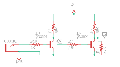
The circuit fragment below was not needed for the experimenter's board but I threw it in anyway. It allowed an external clock signal--say an LFO's square wave--to be split into a logic high (A) while (B) is low, then visa-versa on the next clock edge--the same idea as the output of the T flip-flop.  

However, the CD4027 and its buffer seemed a bit more tolerant of unusual (?) signals to activate the switch; for the final build I will probably use the flip flop, even though it requires more components.

Here are some useless build photos:

Happiness is new boards from PCBWAY!


So how did the DG401 sound? Well.....GREAT. The DG401 switched super fast, no audible clicks, pops, or oddness. Remarkable, really. And you can still find it for sale in P-DIP....and it's not too expensive....

In terms of making this switch switch--I had to do what its datasheet says--S and D are normally disconnected, to make them connect hit the logic pins ("In") with >= 2.8V.  

This meant I needed to power the CD4027 with  >6V or the CD4027's "Q" output was a bit too low.  

So what's next? I will make all the parts so far into a compact Eurorack synthesizer module. One of these days....Stay tuned for Part 4.3. Update: Done! Works! Post is here.


ARP 2600 Voltage Processors Part Four dot One--Recreating its Electronic Switch

Before we begin: Please visit my sponsor's website, PCBWAY; it makes them happy when their analytics tell them I have readers. Click here to visit their homepage and here to find ready-to-fab gerbers for many of the circuits featured in this blog....visiting their websites using these links helps underwrite the cost of new AudioDiWhy projects. Thanks!

======

Hello again....this time I continue creating clones and work-alikes for a few sub-circuits found in Arp's legendary 2600 semi-modular synthesizer.  

ARP 2600. A classic's classic!


Let's design a workalike for the ARP 2600's "Electronic Switch"....

This circuit will be a bit more complex than ARP VP clones found in recent posts.

Breaking this down--in this post I breadboard a buffer and T flip-flop for use in an upcoming 2600 inspired Electronic Switch Euro Module.

The ARP 2600's "Electronic Switch".

The 2600's switch (a "how to use it" video is here) employs a discrete timer feeding a discrete toggle ("T") flip-flop; see the ARP2600's service manual--here--page 29--to peruse its Electronic Switch sub-circuit.


This is a clever design (ARP was clever!)--I simulted the discrete flip-flop using Falstad; get the sim here--a bit tricky; I had to preload the virtual .1n caps with 5 volts and 1mV respectively, then reset Falstad--discussion about creating discrete flip-flops using Falstad is on Modwiggler's DIY forum: here

OK! For the flip-flop section I could have cloned  ARP's design, but that seemed to involve more parts than I thought necessary.

Alternatively I could have used an 8-bit MCU, Arduino, etc., but that would have been too easy:


Why make things easy, ever?


Instead let's use a CMOS JK flip-flop IC....I have too damn many of these in my junk box and have never used a single one in a project.

CD4027--dual JK CMOS flip flop--Falstad sim for T flip-flop is here.

Turning this single IC into a T flip-flop was easy--using the legendary Don Lancaster's "CMOS Cookbook" as a guide (sadly, Don Lancaster died recently--obit is here) I whipped up a CD4027 based T flip-flop on a breadboard:


Here's its schematic:


The momentary switch in the bottom left toggles the flip-flop on data-low, easily modified for data-high:

"IN" is connected to Pin 13 on the CD4027 IC.


When I touched this switch it toggled the CD4027's pins 15 high/14 low to 15 low/14 high, then back. Cool!  

But how do I buffer pin 13 so the CD4027 will work reliably with all the different signals from my bench and modular rig?  

I messed around with different buffer designs; I think I will use the one below--which seemed to work with most of my various triggers, gates, LFO's, VCO's, MakeNoise Arrows Everywhere and so on; the output voltages and trigger durations found on my rig are inconsistent and this levels the field somewhat. 

Breadboarded that too:


Next: how will we switch the audio and CV--use FETs? 

Nope, FETs seem a bit dated, instead, a cool family of parts I found for this: the DGx0x series; an affordable CMOS dual rail analog switch. 

The DG401 looks like a good fit:

 "from the datasheet, I am pretty sure it will work"


Instead of breadboarding a DG401 and an output buffer--I hate breadboarding--I created a DG401 "experimenters' board":


I have laid out too many breadboard-busters and felt impatient, for better or worse I whipped up this one in a couple of hours at most, maybe an hour? and sent off to my ever-patient and endlessly polite sponsor, PCBWAY for fabrication.   

Next time: I will build the experimenter board and tie it to the breadboarded CD4027 T flip-flop/input buffer. 

If it all works, it will then be reimagined into a 4-6 HP Eurorack module to be featured in a future post.  

Fun!

Until next time, flip or flop--better yet, do both! UPDATE: posted...go here.


ARP 2600 Voltage Processor--Part Three--Mixer/Inverter Clone--Finished and Working

DiWHYers: If you want to build this eurorack module, you can get schematics, gerbers, a BOM, board/schematic layout, and more, from these guys; their community (here), and this project page. 


Hello again!  The mixer inverter ARP2600 clone modules are done--in and working!


ARP DIwhy modules with a friend's vintage 2600.  Got USD $14K-20K to spend? you can get an original...

More info about the project and design can be found in part II (here--original clone attempt...)

You also may want to skim part I (here): original thinking behind the ARP 2600 Voltage Processor project and cloning the "Increase lag time" sub-circuit.

Cloning these 3 sliders and their surrounding circuitry!  Euro format....

I have posted gerbers, BOM etc. for two clone modules. One is the equivalent of sliders 1 and 3 above, with a pot controlling normallized control voltages, the other has pots to attenuate 2 input signals; on both, summed outputs are inverted, same as the original.

To build both you will need 2 boards and 2x front panels:


Front Panels. The one on the left represents ARP sliders one and 3.

In general this is a super easy single op amp build, it took me less than 2 hours to make both versions of the ARP 2600 mixer-inverter voltage processors.

2x inverters with the lag processor you can read about here.

More A-B testing with voltage processors in a vintage 2600....


Easy!!!  

More ARP clones on the drawing board...the Electronic Switch for instance? Until then, have fun and don't breathe the fumes.

ARP 2600 Voltage Processor--Part Two--Mixer/Inverter Clone

Before we begin: Please visit my sponsor's website, PCBWAY; it makes them happy when their analytics tell them I have readers. Click here to visit their homepage and here to find ready-to-fab gerbers for many of the circuits featured in this blog. You'd be helping this blog out a whole lot--visiting their websites from the links above helps underwrite the cost of new projects.

Thanks!

======

Let's keep going with what we started last time: cloning circuits from the legendary ARP 2600 synthesizer--specifically it's voltage processor. 

The subcircuit cloned this time is its Mixer-Inverter:

A clone of ARP2600's "Voltage Processor's" top 3 sliders--a mixer/inverter

Original ARP2600.  We are cloning circuity in the bottom center.


Specifically this time we are cloning the functionality of these three 2600 sliders and 8 jacks!

Looking at the original ARP Schematic (here, page 29) the top three "voltage processor" sliders are tied to an inverting op amp based mixer. Simple enough..... 

So what's the big deal? I think ARP's take on this familiar circuit yields a lot of possibilities in a deceptively small amount of front panel space. Brilliant engineering from ARP, I think.

ARP'S DESIGN

The fun begins with the +10/-10 normals. This means with the sliders all the way to the left you end up with an output bias offset of 0V; the inverted output does just that: it inverts the signals you insert to the immediate left of the outputs.  

However if  you increase the pot's value, and/or put a different control voltage into one or both CV inputs, then mix it with an unattenuated input, you can alter the output's bias offset in extremely useful ways.  

Furthermore if you attenuate the unattenuated inputs (using a passive attenuator, or the ARP 2600's VCA, for example) now you have a 6 channel inverting mixer. Or gang 2 of these together to get more inputs....or use 2 in series to re-invert the inverted signal....or...

EURORACK PORT

The original 2600 design has 3 faders, two with attenunated CV normals, another with a normal Keyboard CV so you can quickly realize a Weather Report inverted keyboard vibe.  But--how to best represent this within our beloved Eurorack footprint?  

In my rack I have to save space so I didn't use sliders. And there was no real way to duplicate the "keyboard" normal in my modular setup. 

Instead, I decided to make 2 variations--one that has the pots vary the +CV/-CV normaled inputs--ARP sliders 1 and 3; the other allows you to attenuate the input signals--a dual version of the 2nd slider from the top. 

To get the full 2600 vibe, you might want to build both?

The photos from this post are the latter variant.  The other has the CV and Mix inputs flipped on the front panel and main board.

On to build photos:

Happiness is new boards from PCBWAY.  Show their analytics that you read this blog by going to their website here.


Each variation requires 2 PCB's, main board and front panel.


The op amp is SOIC--not too tiny....


The pots I use for these Euro projects have a longer shaft than will the knob can, so I cut them to size with a Dremel cutting tool:


The trick to cutting the pots' shafts without shattering a bunch of cutting disks--it's time consuming to replace the cutting disks when they break--was to cut one side, then the other, than back to the first. I did this over and over until maybe 1mm existed between the cuts.  

Then, I used pliers to twist off the remaining metal that is not needed.  

After the knob fitted flush with the front panel.

Ready to test!!!


"Seems working"


Ah, an inverting mixer!  It works, but I have thought of improvements to the main boards' layouts to make fabrication easier.

I am going to redesign 2 of the PCB's then go to PCBWAY with hat in hands to see if they will get me some improved boards.  

Then I will create a "Part III" post and make the gerbers and associated files available to you, my faithful readers.  

So!!  Upcoming--improved ARP mixer/inverter clones, and ARP 2600 sample and hold/2600 audio switch subcircuit work-alikes.  Should be ARParrific!  Until then, don't breathe the fumes.