Tuesday, December 19, 2023

DSP-G1: ARM based 4 Voice Synth on an 8 pin DIP

 Readers: If you want to build the project featured in today's post, please go to PCBWAY's Community pages--a gerber ready to download and/or fabricate as well as KiCAD files, PDFs, a BOM, links to Github etc. are here. A quick sound demo of the finished project is here.

Also please visit PCBWAY's site using the link here--it will help this blog immensely. Thanks.

======

A colleague from my geeky audio meetup group sent me a link to the DSPG1 and I thought--$20USD and some jellybean parts gets you an entire 4 voice synthesizer?

The DSP-G1 from Synthetic Sound Labs--datasheet is here


Cool!!

Let's motorize this pursuit....in this post I lay out and populate a DSP-G1 based single-board synthesizer and get it up and running.

ABOUT THE DSP-G1

This is an older IC--a decade old post about the DSPG1 is here.

It's apparently based on an NXP LPC 81x MCU--an ARM Cortex M0+ inside an 8 pin DIP MCU.

I've heard about synths created with Arduino and the Mozzi library--I figured this was the same idea but with a different MCU and proprietary firmware.

MIDI and OPTOS

The DSPG1 has no analog CV in; everything is controlled by MIDI.

In the years I've been pondering audioDiWHY hard to believe this was my first MIDI project. 

Yep. 

I knew very little about MIDI other than: Roland, Obeheim and Sequential invented it, it's 8 bit, it's pretty slow, and it's been around forever. 

Wikipedia knows more, go here.  

A good Hackaday article about how incoming MIDI can be opto-coupled, to eliminate ground loops and other gremlins, is here

I hate ground loops and thus incorporated optocoupled MIDI into the DSPG1's PCB.

I didn't read the Hackaday document carefully enough and consequently Revision 1 came back from PCBWAY and it didn't work (at all).  

After some head scratching it turned out the Opto chip I incorporated in Revision 1 of the PCB was too slow. 

Six pin optocoupler IC designs are not created equal--not even close. You have to choose the right opto IC to get the desired results--if the DSP-G1 couldn't see a decent MIDI signal containing appropriate continous controller values it made no sound at all.


Live and learn?  


Rev 1 of the board. looks OK??


Um...nope. I had to kludge a PC900 optocoupler in place of the 4n25 opto IC. The PC900 had different power requirements and a different pinout. The resulting module "worked" but was unreliable.


The devil in the details: the MIDI spec wants rise times less than 2uS.  The MIDI rise time for a 4n25 opto on my bench was about 45uS! No wonder REV1 didn't work pre-kludge.

I redesigned a REV2 board to accomodate faster opto IC's: PC900 (got some NOS from Ebay)  PC900V (got some cheapees from China) and H11L1M (got some from Tayda); all had the same pinout and roughly the same specs. 

In revision 2, all three six pin optos worked and I got sound out of the module.

Subcircuit for the MIDI optocoupler IC's used in REV2 of the board. Hint: with MIDI sending current to  pin 1, scope pin 4. If you don't see < 3us ups and downs you have a problem.


 Build photos:

New boards from this blog's friendly sponsor, PCBWAY. You can help out this blog by checking 'em out.

Rev 2 Board is a mix of through hole and 1206 SMD.  For some DIY applications--for example, when swapping parts as I hone in on a sound I like--SMD seems easier than through-hole; heat up the part and it comes right off; clean up the pads and drop in a different component.

Rev2 uses surface mount 10uF caps. First time I've incorporated those. Thanks to Elton from Otter Mods for showing me how to incorporate them into Euro SKIFF designs.


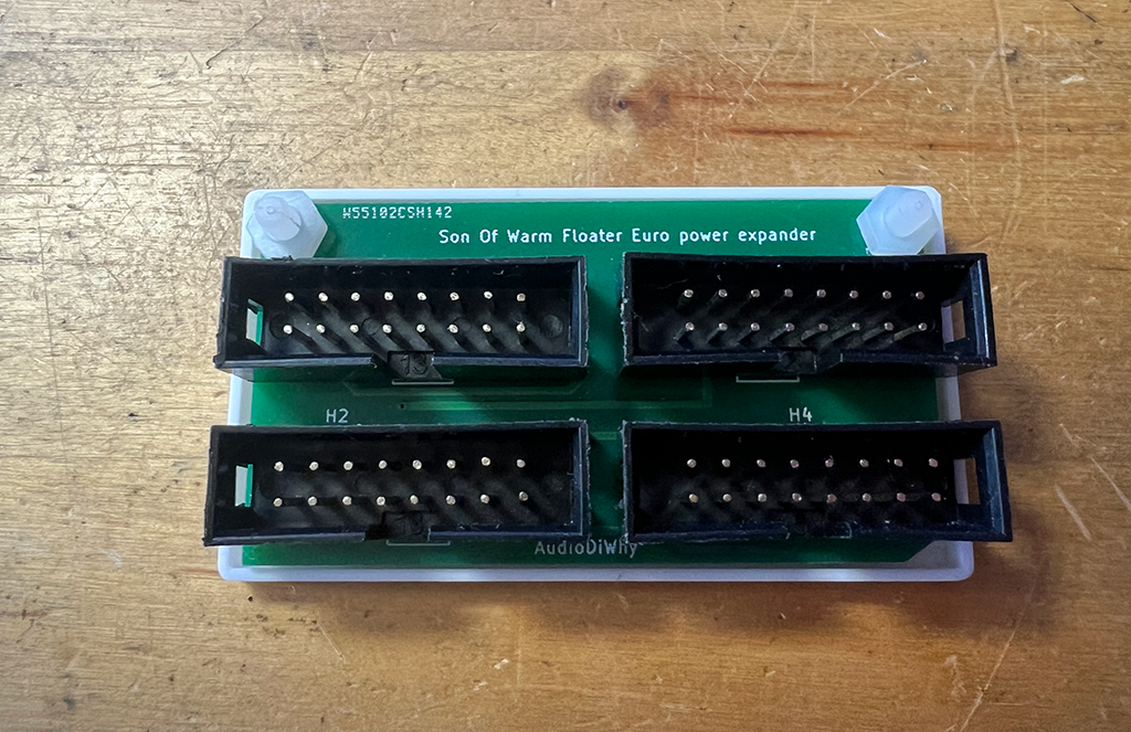
The toggle switch in the center is for power-cycling, necessary to fix stuck notes.

Dumb, dumb! Rev 2 still isn't quite right, it incorporated a switched TRS mono jack for MIDI. I needed a true stereo jack. I ordered the right part from Tayda ("A6685")....this mistake is corrected on the gerber and KICAD files I uploaded to the PCBWAY community site.


Testing and recording the DSPG1 module in with a TipTop Happy Ending power; MIDI CC is provided by Reaktor. Still need to design the front panel...maybe later.


TRS MIDI 

At its physical level, MIDI forms a current loop; if you are using a 180 degree 5 pin DIN jack, pin 4 is "source" for the loop, while pin 5 is "sink". 

This is ideal for driving an LED in an opto-isolator. 

However, MIDI DIN jacks take up a lot of space; in the world of Eurorack space is the thing we never seem to have enough of.  Thus, a lot of Euro designs use TRS 3.5" jacks instead of DIN.    

Let's motorize that pursuit as well:

Bench notes: MIDI DIN to TRS Type A MIDI

I built my own TRS A male to female cable--easy--I got some TRS male to male 3.5mm jumper cables and cut one end off, then soldered it to a DIN5 female using the pinout above.

A good page for different wiring configurations for DIN, TS and TRS MIDI is here. A more in-depth view of the whole enchilada is here.

USING THE DSP-G1

There may be an existing public source MIDI Continuous controller generator for the DSPG1 online but I couldn't find it. 

Therefore I conjured a Reaktor 5 ensemble to generate the MIDI CC's:

Get the DSPG1 ensemble from Github, here.

The ensemble was then opened as a VST plug-in Ableton, using 3 Ableton tracks. 

The Ableton configuration ended up being harder to set up than anticipated.

The leftmost track contained the Reaktor DSPG1 ensemble in a VST (Reaktor VSTs--even if they are MIDI only--can only exist in Ableton audio tracks); a second MIDI track merged note on-offs from a Roland A series controller into the MIDI stream. This allowed me to play notes and adjust sounds at the same time. 

A third MIDI track sent the CC's from track 1 to my studio's MIDI controller, an iConnectivity Mio.


I had to carefully dial in the Ableton configuration above, otherwise I could send Midi note-ons and CV's and whatnot directly to my studio's master bus out, creating potentially eardrum- and speaker-destroying thumps and bumps. If you try something like this at home, be careful!

With everything set up I could make some interesting sounds with the DSPG1, a super-short/super-quick demo recording is on Soundcloud here.  

If I get more time I will expand on this.... everything you hear is all DSP-G1; only plugins used were EQ and reverb.

I created a Reaktor 5 ensemble to generate the CC's (get that from Github, here) but Max for Live or any decent MIDI controller that can generate 19 independent, simultaneous CC values should work.

The filter is 24db, it sounds a bit crunchy but not bad. 

The DCO detune gave me a nice, sort of late Juno-ish sound.  

The paraphonic nature--one VCF and VCA for everything--didn't bother me as much as I thought it would.  

The DSPG1 does not support MIDI portamento, transpose, velocity, or sustain CC's--it does not have memory slots to store your favorite sounds--what you see in the data sheet its what you get. But again, what do you want for $20?

The only issue I had, and it might be my MIDI rig, is stuck notes every now and then. The DSPG1 does not support MIDI CC123 or CC120 "all notes off"....power cycling silenced stuck notes, but I had to dial in my sound again.

So what's next?  Not sure. The DSPG1 is now 10 or so years old, maybe older; I can't find any DSPG1's for sale as I am writing this post. When they are back in stock I might create a front panel for the PCB. 

In the meantime, it's been a good learning experience, especially on the MIDI side of things.

Many thanks to Synthetic Sound Labs' Doug Slocum for invaluable assistance with this post.

Thursday, December 7, 2023

Son of Warm Floater: Intro to FreeCad 7

 Readers: If you want to build the power expander featured in this post, please go to PCBWAY's Community pages--a gerber ready to download and/or fabricate as well as KiCAD files, stl for 3D printing, FreeCAD files, and so on are here

Also please visit PCBWAY's site using the link here--it will help this blog. Thanks.

======

I had so much fun getting started Kicad, why stop there? I needed to replace Fusion 360 whose license fee will go up by  >700% in a few years with something more affordable.

After some looking around I chose FreeCad, a popular open source choice for 3D modeling. 


As a first project I created a tray for an improved Warm Floater (initial post here). The Warm Floater is a small PCB allowing 3 Euro modules to be powered by a single 16 conductor ribbon.  

The update employs box headers in an effort to make it nearly impossible to orient the power cables incorrectly.

FreeCad seemed difficult to grasp at times but after a few evenings I got it working. There are endless youtube tutorial videos about it that got me me out of most jams. 

And I need to remember: it's free. No whining!

3D printed tray printed by my patient sponsor, PCBWAY

Like Fusion360, Freecad starts with 2D sketches and allows you to extrude them (FreeCad calls this "pad") to a 3D shape.  

A few of  the issues I had with FreeCad: 

I was unfamiliar with "constraining" my sketches, locking down proportions. A good video about sketch constraints is here. This makes sense, we don't want our dimensions drifting all over, but at times the sketch looked constrained to me but I still got at least one "DOF" ("degree of freedom") and found I was "under constrained" (since I married my psychiatrist girlfriend, no, but in the world FreeCad, perhaps?)

Doh!! still one DoF!

I couldn't figure this one--I could tug and pull and my sketch would stay put, so what was underconstrained? but--my tray still printed OK. 

Everything with different Z extrusions had to be its own sketch. Maybe. Still trying to figure that one out.  

To make the tray edges for this post's project I had to craft a rectangle sketch on the XY plane, extrude or "pad" it, then "pocket" it, making the tray's Z access edges. So far, so good. 

Next I created a second sketch and constrained two 3mm holes. The second sketch was superimposed on the first. Then I could "pocket" the holes (sketch 2) to push them though the tray (Sketch 1). I could find no other way to do this, and this seemed like a lot of steps to create an extremely simple 3D shape. 

Again, once I figured it out it made sense, but I kept trying to get the holes cut out of the tray within the same sketch--nope.

I printed one of these out on my 3D printer but needed more of them. 

With my tray STL file in hand, I whipped up a simple PCB uploaded both to PCBWAY, yes they do 3D printing, and wham, it was back. The 3D print jobs looked great. I am not saying that because they're my sponsor, really, the quality of the print was top notch. 


Let's build!


3mm nylon screws and nuts fastens the PCB to the tray


This got mounted in my bench rack, now I can put more modules with low current draw in there....much needed improvement.

I figure I will get better at Freecad over time....this still feels very new to me.

See ya next time. 

Friday, November 10, 2023

Warm Floater--Eurorack "Power Strip"

 Readers: If you want to build the power expander featured in this post, please go to PCBWAY's Community pages--a gerber ready to download and/or fabricate as well as KiCAD files, 3MF for 3D printing, FreeCAD files, etc. are here

Also please visit PCBWAY's site using the link here--it will help this blog. Thanks.

======

I solved a simple problem--I had too many Euromodules for my TipTop Happy Ending power supply. 

I didn't need more current, instead, I was out of physical connections.  

I whipped up a "power strip" for Eurorack--one 16 conductor input, 3 outputs. Small and simple....a one afternoon tops DiWHY project.


I laid it out in KICAD:

Using PCBWAY's Kicad Plug-In it's off to the blog's helpful sponsor--boom, it was back:


Building it was a piece of cake.


To test I hooked up three modules "op amp only" modules and checked the current draw--20mA. Fine.


Let's wire it up.


But! what happened if the traces shorted out against the case?  Electrian's tape!

At least I used green electrician's tape!

But then I started to feel--guilty. Why not 3D print?  

Fusion360's license (for me) is going up from $100 a year to $795 a year--nope.

I started to check out an interesting--albeit counterintuitive and surprisingly hard to learn--CAD program called "FreeCad"--as a simple first project.  

FreeCAD and my brain were possibly not meant for each other. Nevertheless I designed a 3D WF Holder ("tray"? "backing"?) and printed it on my MP printer. You can download the 3MF file here and/or get it fabricated at PCBWAY, they do 3D printing all day long.

I had to widen the screw holes a bit to accommodate 5mm screws.  The 2 holes seen at the top of the PCB were enlarged in the uploaded gerber.

DONE! This is when it's good to know some DiWHY as I was seriously out of power plugs in my rack. This was a simple utilitarian PCB that I have not seem in the wild yet--it's probably out there and I missed it, if so, well now there are a few more of the damn things.

Again, you can download all the stuff for your own warm floater here.  

Next time, some MIDI.  have fun!

Sunday, October 22, 2023

KicADSR: First Project Using KICAD EDA

 Readers: If you want to build the module featured in this post, please go to PCBWAY's Community pages--gerbers ready to download and/or fabricate as well as KiCAD files, PDF's, BOM etc., are here

Also please visit PCBWAY's site using the link here--it will help this blog. Thanks.

===================

Back again....from the previous post I switched from Eagle to Kicad for schematic capture and gerber file creation.  

To put KiCAD EDA to the test I laid out and fabricated a Eurorack synthesizer module I know pretty well: Rene Schmidt's "Fastest ADSR in the West".

Good news, the KiCAD based design, in Euro format, was easy to lay out, easy to troubleshoot and rework, and overall, works great. Success!


Posts about the last time I built the ReneDSR (in PAIA's Frac format) are here and here.

I originally laid this post's project with a lot of through hole resistors and whatnot, a 3 board design, but the highly skilled Elton from Otter Mods challenged me to use more SMD. So you will see a lot of 1206 SMD parts in this build as well.

Build photo time:

Happiness is new PCB's from this blog's patient sponsor, PCBWAY.

Two boards: main and front panel. Main board combines hardware and mostly SMD parts to allow the single board 6HP footprint.


Testing as I go--the ICs are drawing correct amounts of current and not heating up.

Testing....

Oh Calcutta! Seems working.


SMD ADVANTAGES

Being afraid of my own shadow I set my bench up for SMD but continued to use through hole for most projects. 

KiCADSR uses through hole (or "THT" as Kicad calls it) components here and there, for instance, the 555 timer IC. 

Why? I didn't have SMD 555's in my junk box. 

Otherwise, for this new KiCAD era it was time to stop being wimpy about THT. 

Here's the thinking:

I don't need a microscope for everything SMD. I have bad eyesight but could work with 1206 sized parts, for the most part, wearing only reading glasses. 

SMD Parts turned out to be easier to swap after initial fabrication. Really? Yes. I soldered a 220ohm resistor between the voltage rails instead of 100K. Needless to say this was not a good idea and the part heated up quickly. 

Replacing a THT resistor in this kinda situation wouldn't have been impossible but may not have been easy either. I could have lifted a trace for instance. With SMD it was easy! I heated up the part's pads quickly with my iron--each in succession--then lifted it out with tweezers; cleaned up the pads with wick and soldered the new part. I also experimented using my rework tool for this. No, all the parts on the board didn't melt off. No, I didn't make a huge mess. I found both processes quicker and easier than using a solder sucker to remove THT parts.

I didn't need as much room to store parts. I have a whole wall of bins for THT parts, but only a few small boxes for SMD. At some point SMD makes more sense in this regard as my psychiatrist wife (no longer my psychiatrist girlfriend--update, we got married) can't give up endless domestic space to my puzzling hobby.

I could put annoying .1uF filter caps on the back side of the PCB to save space.  In fact, I could have distributed parts on both sides, not just filter caps. 

For the KiCADSR I put one .1uF cap on the board's backside, then wondered why I didn't put all the filter caps on the back side. So if you build this, make sure to flip the main PCB and solder on that part.

In general I found I could fit a lot more circuitry in a smaller space with SMD, and too damn much of Eurorack is all about everything being really tiny.

Redoing incorrect traces is easier when using SMD.  This one was hard to believe. I had 3 fixes necessary to get KiCADSR to work:  I missed a trace during schematic capture and 2 of the pins on the 3.5mm jacks were swapped. Quickly fixed. To wit:

FIXES

Three--count 'em--THREE fixes were needed.  To my surprise: not too hard to solder these fixes in with SMD

Elton was right, kludging fixes with SMD was easier than I thought: I prepped and tinned some 22 gauge wire and soldered it to the butts of the appropriate components. I thought this was going to suck but at the end of the day was it easy. Note: the project I posted at PCBWAY community (here) already has the fixes and the symbol library at github (here) has the updated parts.

OUTTRO

KiCAD is vastly superior to Eagle, and SMD is superior in many ways to THT. It's taken me years of being told this to finally take it to heart, but maybe now I have.

Too often I am too set in my ways to move on--until I actually move on--and only then realize I should have moved on a long time ago. Is there a lesson in here somewhere?  Yes, but I will almost certainly continue to ignore it.


Sunday, September 24, 2023

Kicad: Making the Switch

Bad news (for me). Autodesk's Eagle is the schematic capture/PCB layout application--"Electronics Design Automation" or "EDA"--that I've been using forever.  

But starting in 2026 Autodesk wants $749 USD a year for a Fusion 360 integrated version--and I confirmed with their sales team: my existing $100/year Eagle/Fusion 360 license is going away.

Time to say goodbye to Eagle. 

Say Hello to KiCad.


The guys in my geeky synth meetup group have been telling me to use Kicad for years. Now, everyone will be be happy?  

This post captures notes written during my initial exposure to KiCAD 7. 

As usual this blog post is my own trail of breadcrumbs.  If you are thinking of switching to Kicad from another EDA, or are a Kicad newbie like me, the post may be of some use. 

Otherwise, you may want to skip this one.

GET KICAD

$749?  nope. KiCAD is free. Download it here.  

I got the Windows version--not sure how transparent going between OS's will be, cross platform compatibility was poorly implemented in Eagle. Kicad docs say it's transparent; no reason to doubt them. I will try opening PC created projects on Linux and Mac down the road. I had no problem installing it on a few Windows 10 systems.

PROJECTS

Eagle and Kicad allow me to create a "project"; I never used projects in Eagle. Instead, I created a folder using my OS and put Eagle schematics and boards in there--as many schematics and PCB files in a single folder as I wanted; it was easy to have many schematic revisions in a single folder as long as each had a unique filename and the correct file extension....it all worked.

KiCAD is different; it is designed around a single project/single schematic/single board paradigm. However, a single schematic can have "subsheets" (details here--I have not tried subsheets yet).

Creating a new Kicad project creates new helper files and folders, so if I want to create a revised PCB for a given project, or create an additional board (a "revision 2.0" for example) I have to:

  • Use Windows Explorer to create a new folder
  • Copy the original project, schematic, and PCB files into the new folder 
  • Rename the project, PCB, and schematic files to a matching filename (with their original .kicad* extensions intact) 
Automating these steps should be easy using something like Python and Powershell. I will look around for a script or macro for this. I'd be surprised if someone hasn't already created a utility for spinning off versions of Kicad projects, but so far I can't find it.

KICAD LIBRARIES: SYMBOLS AND FOOTPRINTS 

Eagle has a devilishly confusing "device/symbol/footprint" paradigm that makes you pick a symbol and footprint while choosing a component for your schematic. Eagle "device libraries" contain all the necessary elements--the symbol, the footprint, and how the two interconnect.

After using Eagle EDA for over 20 years I still find creating and managing custom or modified devices confusing, frustrating, and teeth-gnashingly counterintuitive.

KiCAD is a HUGE improvement--symbols and footprints have their own libraries and each is managed separately. The user has to make sure pins and pads are laid out correctly, but that's the case in Eagle as well. 

For a good primer on Kicad symbol creation the video here; footprint creation here. The same ideas are used to modify existing objects as creating new ones. It's easy!

Elton from OtterMods, the resident KiCAD expert in my synth MeetUp group, suggested creating a custom personal library composed of symbols and footprints to be used over and over. Some are made "from scratch", some are brought in from snapEDA, some from obscure libraries found on the Internet, some are existing KiCAD library objects with minor modifications.

Following Elton's lead, I created, and will maintain, custom Kicad symbol and footprint repos. I have posted that on github; go here and here.

SCHEMATIC CAPTURE

After only using Kicad for a few hours, I found its schematic capture ability (well documented here) to be really easy!  

A few shortcuts proved helpful:

  • A for adding new symbols; basics like resistors and capacitors are in the folder called "devices".  
  • M for move 
  • D for drag.  This is the same as "moving" in Eagle--you can move a part and the wires won't break.
  • R, X or Y for rotating and mirroring
  • W for wiring; / (slash) changes if you want to allow 90 degree bends in your wiring, 45 degrees, etc.
  • E for modifying a symbol's properties....tap this and a dialog pops up when you can change things like values, display characteristics, fonts, and whatnot--this "E" behavior seems universal to many objects in Kicad. You also get several options for changing symbols for your entire schematic through the "E" shortcut.

Right click > change symbol brings up a dialog to replace one symbol with another. This is the same as right click > replace in Eagle.

I found synchronizing modified or updated "devices" in Eagle into my design cumbersome and confusing. Thank goodness it's much easier in Kicad--edit the symbol using the "symbol editor", save, open the schematic, then issue Tools -->update symbols from library. This brings up a dialog where you can find and replace symbols found in the entire schematic or a subset. The synch process has to be done manually; fine with me.

Tools > assign footprints brings up the dialog where you can assign footprints for your symbols. Again I found this pretty straightforward with one space oddity: to make your choices "stick" you have to click the "Apply, Save Schematic and Continue" button after making your edits--just clicking OK won't do it.


Another Kicad feature: You can modify a PCB and have the changes brought back into the schematic.  Tools > update schematic from PCB.  Eagle can't do this.

There are a lot more options and features of course. Thankfully Kicad's documentation is really good--find it here.

LAYING OUT PCB's

Eagle automatically creates a PCB from your schematic; with Kicad, you have to start up the PCB editor then issue the command tools > update schematic from PCB to see footprints.

The PCB creation documentation (here) has a lot of detail, but I found the basics to be pretty easy once I learned some shortcuts:

  • D  drag a part, moving its traces along with it. If a trace turns green during the attempt it means it conflicts with your relocated footprint--edit the conflicting trace and try again. Otherwise--if you don't remember to hit D--the footprint will move but not its traces and you are left with a mess. Is there a way to make D the default behavior?
  • X turns on the "trace route" tool
  • Page up/page down toggles between layers (front and rear copper for instance)
  • V places a Via
  • Alt + 3 shows a 3D view of the PCB (cool!!!)
  • There are many more shortcuts documented here.

right click -- drag from bottom to top selects everything; right click -- drag top to bottom selects only items fully enclosed. Useful! Video here.

To change trace width, it's easy with Eagle--type in "change width 10 mil" or whatever in the uppermost text box then click on a trace that you want to be fatter.

A few more steps with Kicad, but still not hard:

In the PCB editor, choose Track: use netclass width > edit predefined sizes.


Next, hit the + below then add some sizes to the dialog. (By the way: 40mm-75mm are really big trace sizes--I was messing around with DRC--you probably want smaller traces...)


Hit OK, now you can dial in the track width you want from the same "Track: use netclass width" when creating traces.


IMPORTING FROM EAGLE

Is it too easy? Just digging into this, but so far:

  • Create a new Kicad project 
  • File > import non-Kicad 
  • Import your Eagle file (project or schematic)
  • Auto match layers in bottom left.

I have done this twice and it appears to work better than expected. However if I went to the imported PCB in Kicad and clicked "update PCB from Schematic" I ended up with a second set of components for the same PCB--so, the import seemed best for importing schematics, choosing footprints, and then doing the PCB layout over again. 

Footprints from the imported Eagle brd are put into a new Kicad footprint library with the Eagle Project as the library name--nice! This makes it easy to grab Eagle symbols to use in Kicad. I found I had to edit the imported footprints sometimes--changing a pad name from "a" to "1", so the design rules checker didn't throw an error but I quickly got the hang of it.

Overall the import from Eagle isn't perfect, but all of this seemed much better than starting from scratch.

Update: 2-25-24; Kicad Version 8 addresses any outstanding issues importing from Eagle. Eagle projects, PCB's, schematics, symbols, and footprints now are imported into Kicad 8 without issue. In the Kicad folder crafted for your imported project a "dot pretty" folder and "dot sym" file containing Kicad versions of the Eagle "devices" appear. From here you can copy the footprints and symbols into custom libraries, match footprints to existing 3D images, and all the rest. Fantastic!

"LIVE AND LEARN"

....solutions to things I had to figure out, not immediately obvious to me

Changing footprint descriptions; matching a footprint to its 3D image Surprisingly--neither are available via the "e" shortcut. With the footprint open and ready to edit: file > footprint properties. The "General" tab allows you to change the description; "3D Models" lets you select and rotate 3D images for the footprint. 11-20-23

Changing "drawing sheet" size (the border with title block etc): open schem or PCB > file > page settings. 11-25-23 

Copying items from one project to another: it took me a few weeks to realize I could have multiple Kicad projects open and once and copy things between them. Open Kicad a second time; open source schematic or board; lasso items to copy; control + C to copy. Now, click on the target board or schematic and use control + v.  1-1-24

Creating ground pours: I always forget how to do this...we will start with the front layer:
  • open your PCB 
  • click on this icon:


  • Select F.Cu and GND in the dialog that appears:


  • Draw a rectangle around your entire PCB, doesn't matter where, but make it bigger than your edge cuts
  • Hint: when closing your rectangle right click + "close outline" to complete the rectangle
  • Click B as in "boy" on your keyboard to fill.
  • Run Inspect > Design Rules Checker to make sure the pour is OK.
Repeat the process for the B.cu (bottom layer). 

Cool, but how to turn the damn things off when you want to edit your PCB?
The "toggle your pours on and off" icons are on the left side of the PCB edit screen:


 Good video for this is here2-9-24

OUTRO: GERBERS n' PCBWAY 

In case you haven't noticed by now, Kicad kicks Eagle's butt. Small wonder Autodesk is moving on.

After a few evenings with Kicad, I feel I know enough to create a baptism-by-fire schematic and PCB. Probably a retread of something I made in Eagle? Why not....coming soon.  

HA!!--it works--"KicADSR".  My first Euro module created with Kicad. Post is here.

No, not that kinda gerber....

....I checked out a Kicad gerber creation how-to on my sponsor PCBWAY's site--here.  

Check that! Shout out to Serene at PCBWAY,  she told me I could get PCBWAY's add-on for Kicad--for uploading designs to PCBWAY for fabrication using a single click. 

Instructions for setting up the plug-in are here.  

A useful video going over other cool Kicad add-ons is here.

After installation the plug-in made uploading files to PCBWAY a breeze: I logged into the PCBWAY website, ran Kicad, opened the test PCB, the in Kicad went to tools > plug-in > "PCBWAY Plug-in for Kicad".  

This gerber-ized my file and everything looked to be good to go.

Finally I picked which color PCB I wanted, how many I wanted fabricated, any a few other options; then hit "add to cart".....

Enough for now, this is getting to be long post. Much more KiCAD on the way. Don't breathe the fumes....  


Anything to Clock Subcircuit

Readers:  If you want to build the project featured in today's post, please go to  PCBWAY's  Community pages --a gerber ready to dow...