Monday, December 27, 2021

CON BRIO GATE: Boards Redesigned to eliminate fixes, trace cuts, bodge wires and other Problems. Works!

Boy Howdy! The ConBrio Gate Generator appears to be one of my more popular projects to date, based on blog post hits. However, the original schematic had a lot of mistakes.

Let's redo the board to fix the mistakes. 

Poof--DONE. Redesigned, new one worked without fixes on my bench.

To summarize, this is a +/- 15V synthesizer module that generates gate signals that speed up or slow down based on input data, think of a bouncing ball running out of energy, for example.  

Parameters can be controlled via gate and CV, and a degree of randomness is built in.

For the background on the module please see the original post here; you can hear what it sounds like here.


Better Never than Late: It took me about two years to finish redo/PCB fix. Thank goodness it's done! Get code, schematics, PDFs, wiring diagrams, BOMs etc. from my github, here. You can also see a "project" for this featured on my generous sponsor, PCBWAY's, project site, where you can download the gerbers and/or get the PCBs fabbed, here.

Let's build!!!!

Boards arrived from PCBWAY post-haste....if you need some PCBs fabbed, please help support this geeky blog and check out PCBWAY.


I chose to design 2 PCBs for this project--a main board for the nano and its buffers, and a board for PCB mounted pots and jacks. Hook up wire is used to connect the two.


Construction was straight forward, no real issues, although I didn't label the wirepads on one board to entirely match the other pcb, which was dumb. Maybe in a future revision? At this point probably not, but I have posted a wiring diagram on the github


Front Panel fabrication used a blank Frac 1U PCB and the construction techniques mentioned here and here:


Jacks were placed on POTS PCB, front panel fit, and then the components were soldered:


Next, I double checked the fit then soldered up the hookup wire:


Then I removed the front panel and cut and applied the vinyl label:


Some touch up, clear coat, and other tweaks, tests, and by Gates, we have a decent looking and good working module:


About the redesign: The main "nano" board is more complex than it needs to be. For example, for the transistor buffer for "Rev in" input I used 2 3904 stages; one transistor would have worked along with some simple code modifications. I wanted to have an "inverting input" for "REV IN" on the front panel but ran out of room so it was omitted. This could be easily implemented down the road but would require more front panel space, something becoming hard to find in my ever growing modular rig.  

Also when I first powered this up to test I found that the output and inverting output seemed to lag a bit. The output should have gone from 5V to 0V immediately, but it was more like a few milliseconds for the 5V to make it back to 0V. I remembered that fet based op amps have this issue at times when in series with other CMOS pins, such as what you see on a Nano.  

An LM324/LM358, which has slightly lower input impedance, solved this issue, so that what I used.

Brio Con Leave oh: That's it for this post. I start a semi-lengthy vacation tomorrow, and I haven't had any time off for a really long time, so there might not be a lot of posts in January. But I'll be back. 


Sunday, December 12, 2021

1J24B Pentode: Developer's board = VCA and Timbre Fun!

Vacuum tubes, or "valves" have always interested me; why in some situations do they sound so good?  

I nearly burned down the house building a 5 watt guitar amp many years ago. I soldered the power transformer in backwards. That put further experimentation on hold, but twenty years later it's time to get back to it.

The 1J24B pentode (the bottom thing, Elmo)

абсолютно! I found an interesting pentode in a Ken Stone design--the centerpiece of his tube VCA, here. The VCA uses a Soviet era tube, the 1J24B, which can be purchased on Ebay for about $1 each in quantity. It's ideal: small in size, works with relatively low plate voltage (25-30VDC), and looking at the popularity of Ken Stone's design, works just fine. 

To get started I had to understand more about triodes and pentodes since they are the cornerstone of most tube based audio circuits. You can read a lot about how tubes work online, for instance, this webpage.  I also found two exceptional videos from Uncle Doug, YouTube's lovable guitar amp/hot rod/friendly cats n' dogs repair guy: here and here.  These are required viewing, I think, and made me realize I had no idea how pentodes worked while I was building my 5W amp. For instance, I didn't know that 6V6's, one of my all time favorite sounding guitar amp tubes, isn't a pentode at all!

Now, after some study, I know--a bit more?  maybe. You be the judge.

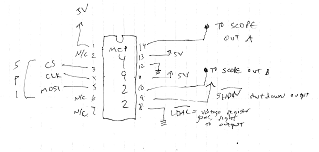
Here is a summary of the components you'll find in the 1J24B pentode:


How it works, quickly: Electrons boil off the cathode when1.5VDC is present across pins 1 and 2; the grid moderates the electron flow; the screen tells the electrons to hurry up (or not), and the suppressor keeps electrons that have struck the anode from bouncing back into the tube's guts and causing problems.  

I am still not sure what pin "3" is for, it appears to be used to tie the tube's body to ground. If someone knows, comment below and enlighten me, because I couldn't find anything about that; in every design I can find it's tied to ground so ve con tierra--go with ground.

Powering a pentode can be tricky, but Ken Stone came up with a clever solution: use +15VDC at the anode, then - 15 VDC for the heater with two current limited diodes in series so the cathode sees the approximately 1.3VDC needed to operate; wire it up so the tube effectively sees about 29.3V from cathode to anode:

Note--In his VCA, Ken uses resistors before the 2 diodes, and puts protection LEDs in series as well, but it's the same idea....

Another tidbit: The 1J24B has a "directly heated" or "hot"  cathode, which means DC (not AC--DC!) is directly applied to the cathode; there isn't an extra filament for the cathode. This makes the tube smaller, I imagine, but also means if there is ripple in the DC cathode supply it will show up as distortion at the tube's output. For what I am doing, any ripple caused by an LED or Diode is OK, but for something really hi-fi, maybe not. In any event, I had not heard of this "hot cathode" idea before.


With the backstory out of the way: to speed up my pursuit of understanding the 1J24B vacuum tube I created a "developer's board".  If you want to follow along you can download the gerber, BOM, EDA files, and so on, for the PCB used in the post you're reading right now, from my generous sponsor, PCBWAY's project site, here.  

Shameless plug: Please help support this blog! check out PCBWAY if you want to get a few 1j24B boards fabbed...or whatever else you're working on.


The idea: break out the floppy, easily tangled, easily shorted, frustratingly exposed bare-ass wire strands that come out of the 1J24B's butt to 100mil pins soldered to the side of a PCB. The diodes and resistors for power are soldered to the PCB, and there are some jumpers to change the basic power setup as needed.  For my build, I used R2 and R3 at 1.5K, and jumped J1, J2 and J3.  R1 and "anode jump" were omitted.  


With the 1J24B, resistors, diodes, and jumpers soldered in place, it's easy to put the 1J24B on a breadboard and start messing around.


Let's Go Get Kenned: Looking further into Ken Stone's VCA, which from bench tests looked more like a voltage controlled attenuator than a high gain amplifier, the fundamentals come into focus. 

With the cathode seeing about 1.3VDC, audio goes into the grid to moderate the electrons flowing; offset CV is applied to the screen to adjust gain, the suppressor is tied to ground to keep things sane, and the output at the "plate" or anode is capacitor coupled, removing the relatively huge DC offset that the 1J24B needs to function. 

The rest of his circuit uses op amps to condition the various signals to work well with the tube. At the end of the day, it's pretty simple, but of course you have to get it right for it to work at all.

Here are the voltages I saw at the bench. Feeding the cathode with about -13.5VDC across its terminals, the plate voltage could be anywhere from about 10V to 15V to get the sine wave to pass with minimal distortion. The anode inverts the incoming signal, and we see a 11-12VDC offset at output. Thus, capacitor coupling and buffering for the VCA output is essential; the tube itself adds very little distortion if set up correctly.  


From here I could present a sine wave at the tube's grid and out came a decent sine wave at the anode.  Incoming CV moderates the amplitude of the output sine wave. So far, so good!


If a tube VCA is your thing, take a look at Ken Stone's design for sale (here). 

But I wanted to see what else I could do--experiment time!  

It didn't take long to come up with a 1J24B based timbre changer or VCF, I am not sure what this really is:

I benched that with breadboards:


I haven't dug into this too much yet, but to me, the screen allowed only certain frequencies and harmonics to pass through, due to the .1uF cap, which caused odd distortions to the waveform at output--a 50% square wave ended up like this for instance:


The waveform at output was adjustable by changing CV and/or input audio DC offset and/or the 50K pot you see above. Fascinating! 

Testing: if you are getting little or not filter sweep, you may have a short somewhere. Check your voltages: you should see about 1.5V between the cathode pins; the grid signal should be AC with a slight DC offset (maybe -2 to +5VDC), while the screen voltage varies based on the CV input.  If you don't, say grid offset is close to -15V, you may have a short in the tube or elsewhere.  

Also I noticed that with a new 1j24B I saw about 30-100ohms resistance across the anode to cathode pins (1-2).  There was no other resistance I could find between the other pins.  If your tube out of circuit tests otherwise it may be problematic.

This might be the beginning of an interesting circuit, so I created a 1J24B footprint in Eagle:


In the copious (not!!) amount of time I have between now and the New Year I hope to refine this idea  by creating a design and PCB for a 1j24B timbre trasher. What would 2 of these circuit fragments sound like in series?  In parallel?  Can vactrols be used for the 50K pot?  Can you tie the output back to the input for--who knows? 

The usual....hours of fun.  Update 2-13-22: a timbre modifier design works on the bench, see the post here.

OK that's it for now. Pretty long post. If you are getting presents for the upcoming holidays, I'd suggest going tubular. Until then, don't breathe the fumes. 

Tuesday, November 30, 2021

Overclocking an Atmel 328P--"Seems Working"

Back when dinosaurs roamed the earth, I worked at a place where one of the dev guys was from Russia, and when you asked if he got his code right, he'd say, in a very thick accent, "seems working".  

Pretty soon every other tech started saying the same thing whenever they were ready to move on.

Boss: "Did you get that rack built out OK?"  Tech: "Seems working".

Boss: "Did you review the code for the new firewall's security policy?"  Tech: "Seems working".

Boss: "Is the CEO OK with his new home theater the shareholders built for him?"  Tech: "Seems working."    

This time I laid out a revised minimalist Atmel 328 development board to experiment with overclocking.  


Yep, seems working.  At least for blinking an LED.  

From various web pages I found (here and here for instance), overlocking these ubiquitous 8 bit MCUs is pretty common, and at least one user went all the up to 50Mhz--that's 30Mhz over what the 328 is designed to run--and lived to tell the tale--but many users caution that overclocked things work until they don't.

PCBs for the overclocking project come from audiodiwhy's generous sponsor, PCBWAY.  Please help out this blog and check 'em out.  

I wanted to mess with the basics, having never overclocked anything before, so I laid out a slightly larger footprint "AVR minimalist development board (post about original design is here) to accommodate basic experimenation. 

Why bigger? I wanted to be able to get my finger onto the MCU chip to see if was heating up and be able to quickly get to the crystal to desolder it and drop in something faster (or slower). 

For experiments sometimes bigger is better, right?

As far as I can tell, after letting a main.c blink code run for about 20 minutes, with a 30Mhz crystal, the Atmel 328P chip wasn't heating up; it didn't seem to be drawing appreciably more current either (I powered the on board regulator using a Siglent 3303 at 9VDC, 100mA max). This seemed almost too easy.


You can get a box of crystals cheap (I paid about $10USB for what you see here) from AliExpress. Hours of fun.  


The populated board is built from common junk-box type parts. It's the same schematic used in the dirty digital LFO, with a larger footprint.

The ZIF socket (chunky blue thing, top right), which would have allowed super quick swaps of Atmel 328's to see if chip A survived overclocking better than chip B, was the idea didn't pan out. The drills I designed into this post's PCB, to accommodate the ZIP socket, weren't big enough in diameter, so I ended up using a normal 28 bit skinny socket for this build. For experiments like this a ZIF socket would have helped, but oh well.  

I have already laid out a REV3 board with bigger drills to accommodate the ZIF. I will get that fabbed as well, um....sometime.....eventually?


Overall you can barely see a 30Mhz xtal indeed runs a blink C program at almost twice the speed of a 16Mhz xtal board with similar design, parts, and MCU. the LED on the left is flashing faintly....junk box! 

Just as expected. 

Here is the test code used:

#include <avr/io.h>

#include <stdio.h>

void Delay(void);

int main(void)

{

//DDRB = 0x20; /* set bit 5 of DDR register which makes PB5 an output */

DDRB = 0b11111111; // 1 is output

while(1)

{


PORTB = 0b11111111; // switch LED on

Delay();


PORTB = 0b00000000; // switch LED off

Delay();

}

}

void Delay(void)

{

volatile unsigned long count = 150000;


while (count--);

}

The Dirty Digital LFO needs a faster output frequency, and it's arguably easier to put in a faster crystal and overclock it than do a bunch of code optimization. But will it still work?  Will ADC get screwed up?  Will the AVR chip turn cherry red? Will I burn down my lab? One of these days I will drop a faster crystal in there, change the FCPU variable, and see what happens.  

For now, time to move on.  At the very least, use a 20Mhz xtal in your C work right?--the AVR is designed for that, even though the Arduino Uno R3 uses 16Mhz.  

You can get this post's overclock experimenters board, BOM, PDFs of board layout, eagle files, etc., from PCBway's, project site, go here. Have fun--quickly! 

Sunday, November 21, 2021

Simple Buffer/Clamp for Analog to Digital Conversion

Hello Again.  

Let's get back to the analog to digital side of things; specifically, a buffer circuit to prepare a signal for an analog to digital converter, or ADC. 

 A genuine Arduino Uno R3 costs about $20USD, has built in ADC's, and you can blow up its ADC circuitry from overvoltage, so you want to treat that with care....

Dedicated ADC chips have voltage limits as wekk--check out the datasheet for the popular MCP3008 (here); where max voltage at input is 7VDC, and ADC inputs can only be .6V over that. This chip costs approximately $3.75USD as of the writing of this post, so you want to avoid blowing up that IC as well.

Design goals for the ADC buffer: 

Must haves:

  • a simple clamp to make sure the voltages presented to the ADC protect the circuitry.  
  • Some way to attenuate the incoming signal.
  • A way to buffer the incoming signal.

Also nice to have:

  • A simple means to set a bias offset for the incoming signal--otherwise an LFO's sine wave (for instance) could get clipped
  • A way to control the output impedence flowing to the ADC IC or MPU's ADC
  • The ability to bring in the signal via 3.5" jack (for Euro modular synth
  • A reference signal to send to the ADC if needed
  • Thru hole design. Easier for bench experiments.
  • Easy to find parts--resistors, caps, PDIP op amps; junk box stuff.

From the dirty digital LFO project (post here), I've hit on something I like that perhaps meets all these goals. 

I whipped up a small board in Eagle and sent it out to this humble blogger's sponsor, PCBWAY, for fab. 

It's back!

Here it is:


Fair warning: for this initial layout I made mistakes; consequently, there were "bodges" or "kludge wires" needed to make the PCB work--in other words, I had to cut traces and solder in small wires to get the PCB to work. 


I will have another set of boards made with these fixes included....again with the help of  PCBWAY who are always enthusiastic and happy to assist (shameless sponsor plug).

Once Rev 2 is in and tests OK, I will upload all of this, but I am pretty confident that REV2 of this design and layout will be good to go.

Designing the buffer: Here's the back of the napkin drawing that preceded the PCB:


It's basically a dual op amp summing mixer with a single input and a zener clamp at output. For a true mixer, you'd add more resistors parallel to R1.....you can find this basic and ubiquitous circuit fragment explained here
 
The offset at 1B + provides the bias offset while "level" port attenuates the signal.  These can be trimmers, more resistors, or whatever, but I had a lot of cheap 9mm PCB pots lying around, so that footprint made it to this design.

Fluffing the Buffer: This post's PCB follows the napkin layout pretty closely, but Rev 1 got into trouble when normalling reference voltages to the two input jacks.

Here's the corrected schematic after cutting traces and soldering in kludge wires:


In Ref'rence: The voltage at INREF, which feeds resistor R1 and the inverting input of IC3A, is formed by R4, R5, and the LEVEL pot (it could be a trimmer).  All 3 values at 100K 1% produce very close to 5VDC relative to ground if you use + and - 15V to power this PCB.  

Again with +/- 15V DC power, for 3.3Vmax output, R5 should be 40K while the pot and R4 are 100K and of course you want to use a 3.3V zener at output, or close.  

You can use an analog circuit simulator to try out resistors values for the circuit reference voltage here; do your math to keep your MCU safe; also please check your max voltage at the OUT pad to make sure the zener is working as a clamp before hooking the buffer into an expensive IC.


The only surviving and fully useless bench photo of a finished REV1 board:


Posting in the buff: With wire fixes in place and errant traces cut, the REV1 board works when viewing its output with a scope, but as far as protecting an MCU, I needed to dive deeper. 

I gave it a try with an Arduino clone:


I didn't use the reference out to AREF in of the Arduino--so there were minor scaling errors, but adding a voltage reference could be added in future designs.

Specifically, The Arduino of choice for this proof of concept was a Pro Micro clone.  

It has a 32u4 Atmel MCU, a great chip for DiWhy because it has built-in USB capabilities; no need for an expensive FTDI chip or clone; all the USB capability is built into the MCU itself. More about USB to Serial conversion in the posts starting here; more about USB and the 32u4 coded with C is here.  

Furthermore, there are "maker" libraries, ready to go, that expose the 32u4's USB capabilities with simple methods--for example, you can use this same USB-ready MCU to emulate an HID USB Windows keyboard--more in the post here.  

This time I am using the very capable  MIDIUSB library from the Arduino folks, to test the buffer. 

The simple Sketch language code below allows the user to control MIDI continous controller 72 on channel 1, and assumes the ADC buffer output is wired to the Arduino's A0 input.

#include "MIDIUSB.h"


int x = 0;      

int y = 0;

 void controlChange(byte channel, byte control, byte value)

    {

    midiEventPacket_t event = {0x0B, 0xB0 | channel, control, value};

    MidiUSB.sendMIDI(event);

    }

void setup() 

{

//Serial.begin(9600)

pinMode(A0, INPUT); 

}

void loop() 

{

   x = analogRead(A0);

  y = map(x,0,1024,0,127);

 //Serial.println(y);

 controlChange(1,72,y);

/*next line debug "Arduino-style" */

//Serial.println(y)

 MidiUSB.flush();

}

It works with this Arturia Solina Plugin; the frequency sweep was generated by the output of an LFO Prime module. I could amplify its signal to 20V P/P--in other words, way above the maximum 5.6V DC--but the zener clamped this errant voltage to about 5V and the MCU was fine.


Cool!

I might flesh out this idea and post to github finished code and PCBs for a dedicated Control Voltage to Continuous Controller ("CV to CC") module in a future post.

And yes, there are other ways to do this--for instance, there are software CV to CC plug-ins out there--but this soimple hardware and code so this is how I did it.  

Code-ah: No need to power the Arduino externally--USB does that, but I had to tie the ground from the buffer board to one of the GND pins on the Arduino. The buffer during the test was powered the from a simple Frac power supply (post here on how to this linear supply).

As far as improving/modding the buffer circuit, a voltage reference board or dedicated IC could be used instead of the R4/R5/pot network; you could use jumpers to select the reference voltage from a series of resistors; and the PCB could be made a lot smaller using SMT parts for inclusion into a project, but this board is more for bench experiments and designed for simplicity. Good enough.

Best of all, for this board, with all the parts laid out on the bench, it should only take a few minutes to build. 

I'll get more of these made, possibly improve on the CV to CC proof of concept, or to incorporate into a larger project, and post the whole thing, down the road.  

Until then, don't buffer the fumes!


Wednesday, November 17, 2021

Long Live FracRak! Frac Power!!

If you're going to build your own audio gear, you probably have to put it in a case, right?  Enclosure?  Rack?

Indeed, that's where the choices start. 

My DiWhy friends work with Euro mostly for their modular synthesizer projects, some MOTM, and a few the social media savvy "kosmo" format.

My geek audio buddies still aren't sure why I build almost exclusively in Paia Frac, but I'm sticking to it.  

It's a pretty uncommon format, but this week as I was blowing up power supplies I was glad I use to it rather than some of the more popular choices.

+/- 15V Frac power with temp front panel....

I was doing some recording when all of a sudden from my noise generator came a nasty 60 cycle hum.  Not all my modules did this, just a few, and I quickly traced it to one of my original (circa 2003) Frac power supplies. that powered the noise modules as well as a few balanced modulators.

I have already posted building a custom 15-15V linear supply (post is here).  

I hate 60 cycle hum, and it's more fun to build something new than fix broken, so let's build another.  

Frac power is modular, like everything else about it, and modular engineering is good engineeering.

A new linear supply for Frac is easy--especially when you have brand new boards provided by my generous sponsor PCBWAY--and uses mostly junk box parts:


I plugged in the new supply to test--second time in a day!!--SMOKE!  

This blew up a surplus16VAC 40VA wall wart as well as both of the regulators.  

Hello?  

The diodes used to safeguard the regs from reverse voltage looked like chunky diodes in my junk box, but turns out they were precision low value high watt resistors. 

Ooops.  that's what you get when using junk box components and a lack of caution and patience.

Not a big deal to replace impacted parts and put in diodes where they are needed; now it works.

The good news: when you have a power supply problem with Frac, it doesn't take out your whole rig, and conversely, if you have a bad module (DiWhy--that will never happen right?) it won't take out your rig's only power supply.  

Frac is also a reasonable size, not too tiny, but not like MOTM or Moog or synthesizer.com formats where it takes up your entire living room;  Frac is affordable, fits in a 3u 19" rack case, and maybe best of all, PAIA is a cool small mom and pop type company, left over from the phone-phreak/Radioshack electronics geek 70's. There aren't too many of those any longer.

Note that PAIA supply I laid out and built (this clone is based on some of PAIA's earlier 9700 series designs, but beefier in terms of sourcing and sinking more current) use a ton of .1uF caps close the the .1mil DC headers. I discussed these inclusions with some pro EE's--I am not one--and was told that all these .1uF caps makes no different close to the headers and can be omitted--these filter caps need to go on the modules that are being powered, not here. 

So for now, you can leave 'em off.  I have left them off my recent builds and can't hear any difference with ripple, buzz, or other unwanted distortion.

You can download the gerber and BOM for the power supply I use here from PCBway's project page, here

Please help support this geeky blog by checking PCBWAY out and consider using them for any fab work you dream up.  

If you come up with any sort of mod or change to the power supply comment below, I am curious what you folks, my trusted readers, come up with.

See ya next time.


Saturday, November 13, 2021

MCP4922 Library for Atmel 328 MCU--Simple Low Cost Dual DAC Made Easy

Quick one this time.  I'm continuing coding in Embedded C for Atmel 328 MCU's, this time to write a driver for an inexpensive and useful Digital to Analog Converter--a DAC--The MCP4922 from Microchip. 


Datasheet is here--the 4922 is inexpensive, available in a DIP package for easy breadboarding, and  easy to program. This is a good chip for Audio DiWHY.

Let's get to it.

For my tests I wired it up like this: 

Wired this up on the bench:


The toolchain is my usual: Windows 10 running Atmel Studio 7; an Atmel ICE programmer, and a minimalist 328 development board of my own design that I got from my generous sponsor--PCBWAY;  read about the board here and order or get the gerber here.

The library didn't work at first--that's because I made a stupid mistake. The datasheet clearly says to make this chip work with SPI you do a CS pulldown, send 16 bits on each clock, then do a CS pullup. 

But I missed that while reviewing the datasheet, and the SPI3.h library I wrote/borrowed/revised  (post here) didn't have this exact cadence. I literally woke up in the middle of the night realizing what I had done wrong, and it took some will power not to go to the bench at 3AM to fix it. Next morning I wrote this addition to the preexisting Atmel 328 SPI3.h and SPI3.c libraries:

uint8_t SPI_TransferTx16_SingleCS(unsigned char a, unsigned char b)
 {
unsigned char x;
SELECT();
x = SPI_Transfer(a);
x = SPI_Transfer(b);
DESELECT();
return x;

 }

where a is MSB and b is LSB.

Fixed!

 Now I can see both analog outs on my scope:


And can also spy on the SPI using Pulseview--looks right:


Using the MCP4922 library.  The files you need are MCP4922.c and MCP4922.h. The rest of what I githubbed are simple examples and support files.

As of the writing of this blog post, here's a really quick rundown of the functions in the library:

/************/

/* output_4922  send data to outputs of chip.  

In my example, 0 = 0V, 4095 = about 5V.

  data is 0 to 4095; channel is 0 for channel A, any other uint8_t for Chan B 

 default chan A, unbuffered ref, gain 1, no shutdown */

 output_4922(uint16_t data, uint8_t channel) 

/* the 4922 has a buffer for the reference signal.  In case you want to use a reference that has a very low source current.

enter 0 to shut off the ref buffer; any other number < 255 to turn it on.

*/

 buffer_4922(uint8_t buff)

/* gain_4922--for highly accurate output, you can use a 2.048V reference.

enter damnloud = 1 for gain = 1, enter 2, any other number < 255 that's not = 1, for gain = 2 

Apply your 2.048 ref, then turn the gain up 2x. Now you should get, 0 = 0mV at output, 100 = 100mV a output, 1022 = 1022mV at output. 

Should be damn accurate! Very cool  */


/* 

enable_4922_output

enter 0 for silence to kill the 4922 analog outs and put the chip into low power mode

any other uint8_t to make it operate normally.  */

enable_4922_output(uint8_t silence)


/************/

That's about all the chip can do, so that might be all I code for this, at least for now.

You get my embedded C library for MCP4922, along with the example code for making the traces move at my github, here. The updated SPI library is here. I'll be using it in future posts. 

Until then, don't breathe the fumes!


A guy OK with C tries to learn C++. Bjane me Up, Stroustruppy!

Why no posts so far for 3-2024?  I have been woodshedding, brushing up on C++ skills.  What got me to finally start digging into C++? I was ...