Hello again. I've not been posting as much lately due to health issues, but still had time to mess with some new ICs on the bench.
This time I went to war with Analog Devices AD5761/21 bipolar DACs.
 |
| AD5721/61 requires +/-15V, a 2.5VReference, 3 data lines for SPI, and 5V to tell it what is logic "high". Add Pulseview to analyze why it doesn't work and you have a lot of bench clutter. |
DACDAC go: The advantages for audio design using a bipolar DAC, especially one with a buffered output like the AD5721/61, is lower chip count.
Hook a bipolar DAC to your MCU (for me, on the bench, an Atmel 328P on an Uno R3, programmed from Atmel Studio 7), write a few lines of C code and the result is a nice bipolar ramp wave--or any other bipolar low frequency analog signal--at the DACs output. No need to use op amps and/or caps to get the output to straddle 0V.
Perhaps an entire complex AudioDiWhy circuit can be built using only two chips and a few caps: the MPU and the bipolar DAC IC. 16bit fidelity. 20hz-1Khz or so waveforms. Low noise floor. Nice!!
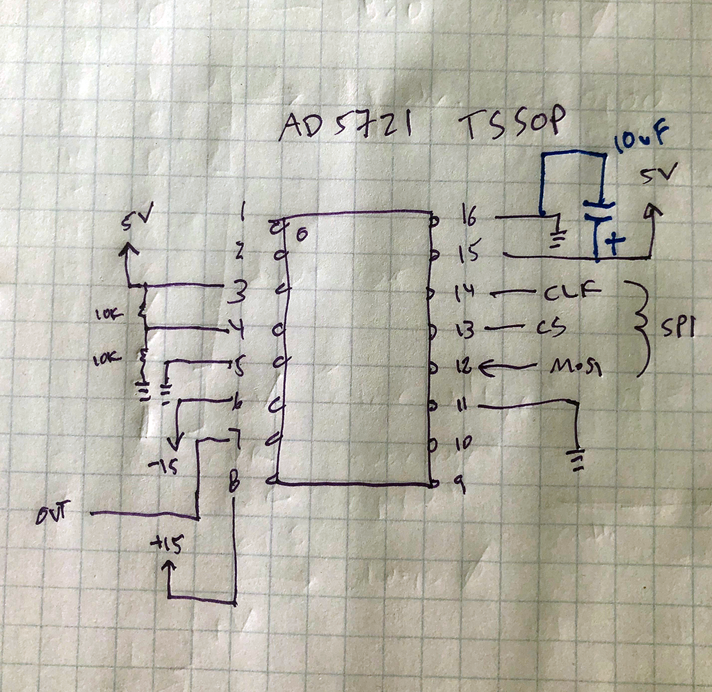 |
| Minimal write-only wiring for TSSOP version of the 5721/61. You can use 2.5V from a bench psup for pin 4, which is the DAC's reference, instead of 2x 10K resistors from 5V to ground. If you want to read data from the 57x1 as well as write to it, wire Pin 10 of the DAC to your MCU's MISO pin. WARNING! Wiring for the LFCSP version of this IC is different--don't misread the datasheet..... |
These 2 DAC IC's are a bit expensive--the AD5761 is 16 bits and costs about $10 USD in small quantities while the AD5721 is 12 bits and costs about $7.
One the projects I've been thinking about only needs 12 bits, so for starters let's be frugal and use that.
 |
| The AD5721 is a very tiny IC and we need to make it ready to breadboard. OK, for tiny tiny tiny SMD to DIP applications I like Schmartboard--more expensive than most SMT to DIP adapters but quick to fab and easy get right. And sometimes they have blow-out sales, which is how I got these adapters for about $1USD each. |
On paper the AD5721/5761 has some other cool features, like the ability to change its output range from your code (no need to use a processor pin for this). Also the ability to read what is in its registers back to the MCU via SDO > MISO. It can output its temperature and daisy chain several of the DACs together for multi channel output.
OK that's the good news, but here's the bad news: I worked for about 3 days to get the AD5721 to do anything (other than just sit at 0V at output) and--nothing
Welcome to DAC HELL!!!!
I swore, laughed, and I cried. I sat up at night trying to brainstorm what I was doing wrong. I went into full OCD mode complete and at times was not able to talk to anyone.
I read over the data sheet 1000 times then another 500 times to be sure I didn't miss anything. I poured over the timing diagrams and used Pulseview to verify SPI was within the chip's speed limits and the chip was receiving the SPI traffic intended (it was).
It could have been my chip? My SMT to DIP soldering work?
I built a second one. Same thing.
I tried all different variations of my code. Nope. No output.
I was coding it wrong? Um, from the data sheet, I am going to say no. But maybe--yes.
I need to explain this.
First let's talk about how to program this little beast.
As DACs go, this one is a bit harder to set up than say a MC4725 but really it's not that bad.
The AD5761/21 uses SPI. It needs to see 24 bit words but that's easy--pull CS down, send your clock and data using 3x SPI transmits, then pull CS back up.
So......
- Power up
- Send a reset (a byte followed by 2 "don't care" bytes)
- Send 3x control bytes to tell it things like what output voltage range to use
- Send a byte to say "send the next 2 bytes to the DAC register"
- Send two bytes to the DAC register. That's the data you want at output.
- Wham Bam--you have output. Right?
- Um, with the AD5721, no. I tried. I really did try.
Nothing worked, so I tried the 16 bit version, the 5761.
YES! Dropped it in, same code, same bench setup, same footprint--it worked!!!
 |
| Output from AD5761, see how easy that is? TWO POINTS! |
But same everything with 5721 (again, I tried two) NOTHING!
I will skip the photo of the scope flat lining.
I have read the AD5721 datasheet more times than I've perused barf bag instructions on a commuter plane--says other than the 4 LSB's of the data registers being "don't care bits" on an AD5721 there is no difference between the 2 chips.
The input register on the 5721 ignores the last 4 bits, but the control bits for BOTH CHIPS are documented as being 24 bits wide.
How can that be when the 5721 ignores the last 4 bits?
So my guess: the control words for the AD5721 must be different than the 5761. That's why the former doesn't work. And AD didn't document this difference in the datasheet correctly. (right?)
And oddly I see posts online for AD5761 uses, libraries for it, etc., but really nothing for the AD5721.
Does anyone even use the AD5721?
Maybe someone can enlighten me, if you have ever gotten an AD5721 to work please, please comment and let me know the data words you used to get the chip to do--anything.
But for now it's 16 bits for this project.
I am going to see if anyone at Analog Devices can tell me what i am doing wrong for the 5721....but they are big, and I'm not, and I may be out of luck.
Update 7-19-21 after asking around and calling in a few favors, I may be able to have a pro EE help me sort this...he has contacts at AD.....AD says no, the control register for AD5721 is 16 bits, in spite of what the data sheet says, so that's not it....16 and 12 bit chips should be interchangeable, but really, they didn't know, and figured I was doing something wrong....to their credit, I am told Analog Device's support on this matter was attentive, polite, and overall top notch.
UPDATE-7-24-21 Giving up on 5721 but the 16 bit version works OK. See the post here. This one goes into the "never figured it out" crap can. I gotta move on......


No comments:
Post a Comment