3x Passive Audio Attenuator: One Hour Build!

Time for another easy one, and maybe my shortest AudiodiWHY post to date, which may not be a bad thing? Simple Passive Attenuator.

You can build something like it out of junk parts, but it might get used a lot!

No decal--skipping straight to FPE finished module looks like this:


I needed this module because I have gotten into Eurorack recently  and there seems to be not a whole lot of consistency in output P/P voltages. Some of them output (say) 2V P/P while for others it's about 5 or 7 or 10V P/P.

Maybe that "hot" output signal needs to be turned down so the next module doesn't distort--since we know it's never cool to smoke Doepfer. But the good news: it's easy to attenuate them hot signals using something like this:


I built this up out of junk parts and an "alubase" panel I had leftover from a PCBWAY order.

Here's the obligatory photo of the back:


Another bonus: I am a rare but devoted Frac guy, and Frac power supplies can get a bit over sized; they can stick out into the module next door when you beef 'em up, which you usually need to do. Putting a passive panel, with no PCB sticking out the back, next to the Frac's "wing" power supply keeps things from shorting out. Thank goodness!

Not much more to say here except it's fun to think up passive modules--i.e., no need for DC power. Can a Low pass gate be passive?  Yep. Can a distortion module be passive?  Yes--check out the previous post here.

Hours of fun, maybe not? but an hour of fun?  yep.

OK it took me less time to write this post than build this module but not much. Again maybe not a bad thing. See ya next time.


Quick One: Front Panel Express

I'm still looking for a way to DIY small quantities of professional looking front panels for projects, but until recently, no dice. I've written about using decals on metal, but that process is time consuming, hogs your oven ("sorry honey, no dinner tonight, I'm cooking my nerdy front panels"), and takes a fair amount of practice to get good results.

And, even when decaling comes out spot on, compared to the real deal, it's still a bit lacking. They're decals!

I may have found the answer--I finally broke down and got my first panel from Front Panel Express (in Europe, same sorta thing here).

Good news, it came out looking really good I think, and was easy. (No I don't work for or get any sort of promotional consideration from these guys).

Front Panel Express' "Hammer Cocktail" panel
Same thing--metal from PCBWAY and graphics via Adobe Illustrator and Lazertran

The panel you see at the top of this post cost me about $59 USD including shipping, tax etc., compared to about $10 each for bare metal and decals, that's a lot more piasters. It would have come down a bit per panel if I bought more of the same design. You know: "The more you buy, the more you save." Shipping is free for orders over $50 and shipping alone for the panel here was about $12USD.  A lot of shipping dough I think for a single 1oz scrap of metal....but it came in a beautifully packaged, carefully prepped box, no way it was going to get scratched or smooshed on the way to my shop and the whole thing came out, really, perfect.

To use Front Panel Express you have to use their software. No choices--it's their way or the highway. Sadly you can't say send these guys a gerber and they'll make a panel from that (which you can with PCBway--use "alubase" and black silk screening).

I tried this FPE CAD software a few years ago and failed horribly; I couldn't even get a 1u Frac panel sized, much less the drills and whatnot. But this time for whatever reason--maybe more time working with Eagle? I was OK. Turn on the grid, draw the panel, no sweat.

Good news is: FPE has the ability to import graphics from a variety of formats. This is very helpful! For me I prepped the artwork (including little circles for drills) in Illustrator, moved it into Photoshop for some touch up, saved it as a print quality PDF, then laid it over a blank 1U frac panel in Front Panel Express' designer app.  Then, used drills in the FPE designer to punch the holes right over the art. I was nervous that thing wouldn't line up when I got the panel (which would have been $50 odd bucks down the toilet?) but, worked great.

If you want to engrave your panels for a more Moog/Synthesizers.com type look you can do that too (how to here) but for me, graphics is just fine.

So now I'm going through other modules where the front panel came out a bit butt, and I'm finding it super fun to make FPE panels, since you can go hog wild with graphics. For instance, further immortalize Don Buchla's photo on your DIY "source of uncertainty."  Why not? I am going to convert more of my homemade panels to FPE over the next few months, it just looks more professional.

OK that's it for this one. Perhaps the mo-fessional part of me that wished I had Bob Moog's chops will kick in.  Until next time, don't breathe the fumes.

GABBAR--High Performance AR/ASR

There are those who think outside the box and there are others for whom there is no box at all, gabbagabi from the EM forum is the ladder!

gabbagabi and I started corresponding after the "FAITW" posts; we are both interested in high performance EG's. In his messages, gabbagabi said he had designed a AR/ASR that attacks around 1ms and is still  musically useful. He sent me his schematic and I (embarrassed to say) couldn't figure out how it worked.

Hmm.

The GabbAR uses a couple of opamp stages as comparators. There is a 100nF cap in there that blips the comparator to start the attack. For me AR's were always 2 diodes, a cap and a couple of pots, and sounded like, well, an AR.

I tried putting stages of gabbagabi's design into a SIM site but the results were--inconclusive?

Gabbagabi reassured me he strip-boarded this ASR a couple of times and it worked great. We traded Eagle files; even though gabbagabi usually uses a design program called "Sprint Layout" he ported his work to Eagle, which is what I've always used. Thanks dude! Also, gabbagabi wanted to fab what he calls a "humanized" PCB, meaning that the PCB is laid out to roughly match the schematic--which takes more PCB space, but makes understanding what's going on and troubleshooting/modding a lot easier. Something I've not seen before.

I sent a gerber of his humanized design to fab along with some other things I was working on, it came back a week later, and I built the GabbAR in a couple of evenings. Guess what? gabbagabi's design works and sounds friggin' GREAT.

It says AD CSLAMMY on the schemo--that's my EM avatar--but this is Gabi's work.

The AR does fine with +/-12V DC or +/-15 supplies, and its outputs scale based on the supply voltages. So for me, in Frac +/-15V land, the max output of the ASR is about 7.5V.  That works.

Gabi's "humanized" PCB layout....

You can mess with C7 and the pots (use audio taper, I think it sounds better) to get sub 3ms attack and to my ears--no click.Very nice! Of course bigger caps and/or bigger pots mean longer AR times. gabigabba suggests using 100K pots and 100uF for C7 for "normal" AR speed, or 1M/2uF for very fast AR.  For me, I ended up putting 10uF and 100uF caps for C7 on a switch and using 12mm 100K audio tapers. So: If you build this AR, you may want to mess with the values for C7 and the A and R pots.

One gotcha: make sure the transistors used for T2 and T3 match the schematic.  Depending on what you use, you may have issues. I used a 2N3906 which was silk screened correctly on the PCB but had to flip a 2N3904 to get this to work. Follow the BOM, bottom of this section.....

I also added an op amp buffer on a tiny daughter board. Now, I get inverting output from about 7.5V to 0V in addition to the native 0V to -7.5VDC and 0 to 7.5VDC "native" output signals. 1001 uses.


Testing....

More testing. Daughter board gives me an additional inverting output....

Once I had this EG up and running I tried to figure out how it works, for anyone truly interested please read my explanation docx here. I'm not an EE so please, feel free to comment or message me if you have other ideas about how this board works--it's tricky.

You can get the PCB and the usual downloadable dookie (BOM, gerber, etc) here.

Finished; UPDATE! I replaced this home made front panel with one from Front Panel Express a few weeks after taking this photo. Maybe one of these days I'll take a picture of the new and improved panel version? 

Going Forward: gabbagabi and I have been IMing again; it'd be nice to shrink this design so 2x or 4x  fit in a single board and (am I really saying this?) see if I can get this shoehorned into the smaller Eurorack format.

But that's for another post. In the meantime it was super fun working with gabbagabi on this. I hope to post more of his stuff down the road. So until next post--go ahead, take a whiff, it's June!

Hammer Cocktail--Low Parts Count 4069UB based Low Pass Filter


Привет! Continuing from last month's post re: using 4069UB CMOS chips. The grunge alternative to boring op amps!!

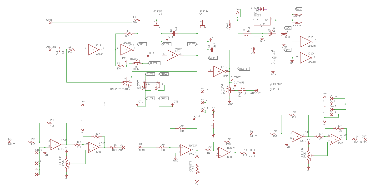
This time, I build a low parts count low pass filter design from the mind of Russian techno master HAMMER. Good news, it's a quick build and sounds like nothing else I've heard, maybe a bit like an MS10 filter but not even that. This thing presents icy cold and then suddenly screams like a gorilla in heat. So: if you're after a pretty sounding 3320 based Chariots of Fire VCF this one isn't it. But for me, when pushed really hard the Hammer Cocktail sterilizes frogs at 20 paces. It's an interesting addition to my DIY rack-o-filters.

UPDATE!! 6-14-19 new front panel from Front Panel Express.  More here.


Front panel made using Lazertran decaling. 

Sound demo is here. About the demo: I pretended I was scoring a 70s US TV sci fi detective series called (of course) "Hammer". But, to not fry speakers, I toned down the really obvious distortion a bit. You can hear bits of it coming through and that's all from the filter.  No outboard distortion used.

The design:

The schematic for this VCF is way less complex than it looks--a simplified schematic can be seen at the top of this E-M post.  It's really only a few parts, and I  like low parts counts....and I hate stripboarding.


For the prototype I included 3 buffers on the PCB (the op amps on the left) since I figured something, not sure what, would have to buffered. I ended up using 2 of them to buffer incoming CV and outgoing audio.  For the output buffer I needed about 8x gain so I used appropriate resistor values--your own setup may require different buffering.

You can get the PDFs, Eagle files, BOM etc., on my website here....the PCB could be made much smaller and really ambitious DIYers could probably fit 2 of these Hammer Cocktail VCFs on a single Euro 14-18ishHP panel.


But for me, I took the easy route, and the over sized PCB was put behind a 1U FRAC panel.

Warning and an aside: I am running out of space in my studio and thus getting into Eurorack, which from a DIY standpoint is much more challenging; Euro is small compared to Frac or 5U and thus, space is much more constrained. That means DIYing surface mount, skiff boards, and the like. You'll se more Euro fab in the coming posts.

About the Russian 4069UB chip: Hammer tells us that the Russian equivalent of the 4069UB "screams wilder" so I bought a few of them from the former USSR. They showed up a few weeks later looking like the vendor forget about Peristroika. These things were beat!


But it wasn't hard to bend them back, to me they were built a bit tougher perhaps than western CMOS ICs.

Nota Buena! Hammer tells me older K561**2 chips might sound better--look for old daycodes (8712 means dec 87 I think?) and round logos--which he says are better sounding

I dropped the Russian IC into the Hammer Cocktail circuit and yep, the Russian 4069 equivalent did sound different, and maybe a bit more "Hammer Like"? Hammer says the Russian version has less distortion, perhaps allowing me to push the filter even harder before it became audibly intolerable. Hard to say, but it was only about $20US for the chips on Ebay, including shipping, so you might want to check it out.

For CV Hammer says use 0-2.5V and power from 5V DC.  I powered from 5V alright, there is a 5V reg on my Hammer PCB since Frac is just +/- 15V.  The resonance pot, which adds the insane uber MS10-like distortion, isn't linear, the interesting distortion is in the upper 15% or so of the pot's travel. I have confirmed with Hammer that for this particular version of his filter this is normal behavior. I might try replacing this with a reverse audio taper pot down the road.

OK that's it for now.  I still have a high performance EG and Lunetta circuit on the bench, more collaborative projects with other DIYers. More on those soon, I hope, but until next time, Прощай


A Rolling Stone Gathers no CMOS--the 4069UB Chip

Time to get back into CMOS stuff, this time the 4069UB (unbuffered) IC used in an analog realm....


What got me started down this particular AudioDIY rabbit hole was an Electro-music forum user "Hammer's" 4069 VCF design--see the post here.  He also has a cool but unassuming Youtube vid of his 4069UB LP filter here. Good work! Even more intriguing: he's from Russia and writes that his creation "screams much wilder" with a Russian version of the 4069. Indeed--got to check that out.

How can something simple sound so--gnarly?  Must be those 4069s?

I dug in and found a really good Hackaday write up about 4069UB's used in analog audio work here and here. Hammer contacted me about his design, and suggests another good source about 4069s used in audio, here.

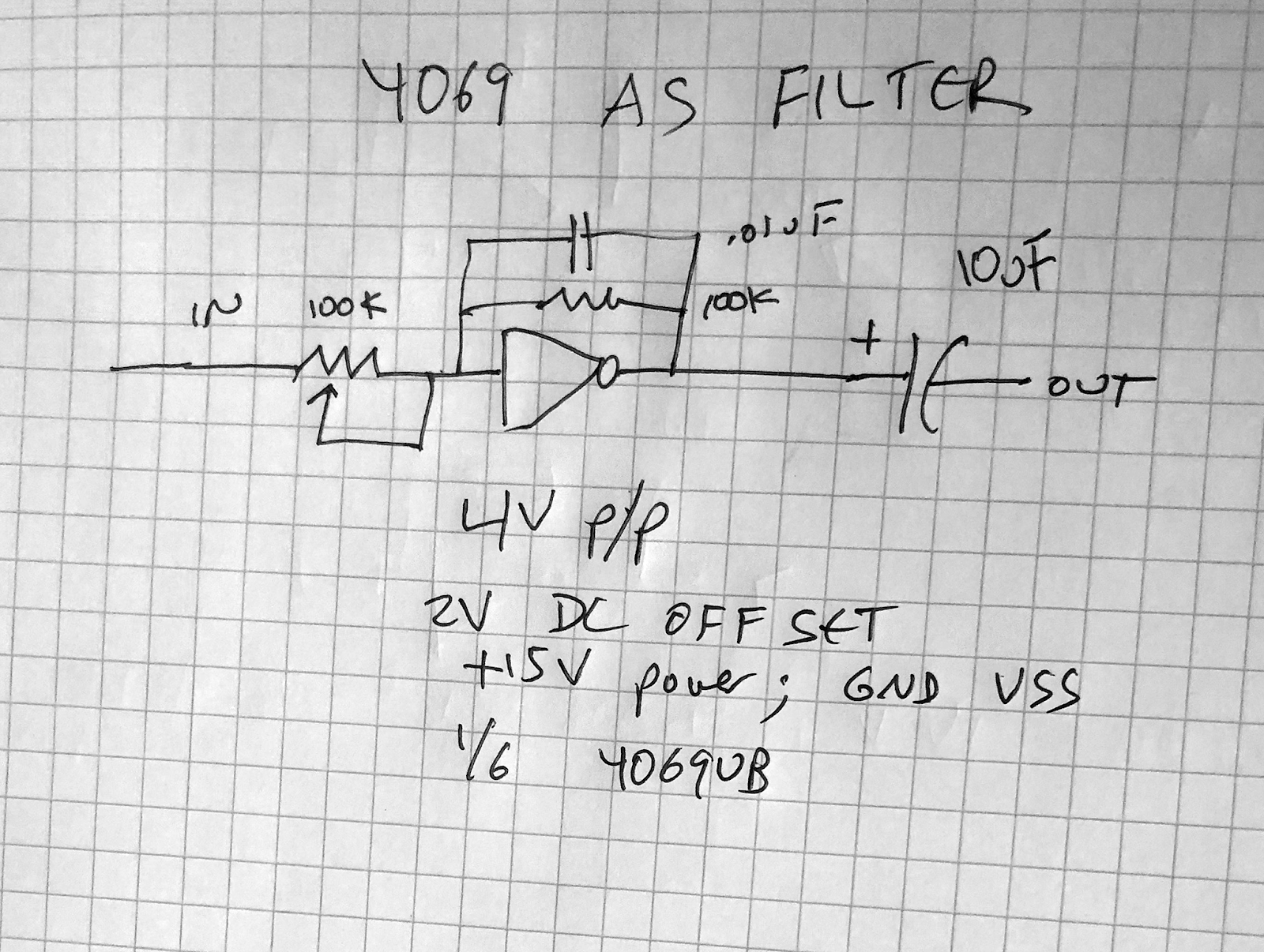
The 4069UB chip, in this get up, is configured somewhat like an inverting op amp. There's a negative feedback loop needed to do useful things--again the Hackaday article lays out how it works; I won't repeat that here.

OK, then, why bother using a 4069 at all (besides getting the equivalent of 6 op amp stages for 50 cents US?)  Why not use a damn op amp? Bing! distortion!  From messing around on the bench: them 4069UB's love to distort.  You crank down the positive rail--distortion. Crank up the incoming audio--what was that then? Um, distortion. I figure you can make a 4069UB **NOT** distort but for squeaky clean applications I'll use an op amp; when I want some grit I might consider a 4069UB. Best of all: to my ears, the 4069's distortion is a bit tube-amp-sounding and OK, sometimes I like that.


4069UB buffer! You need a 4069 with UB in the name for any of this to work, must be the un-buffered IC.

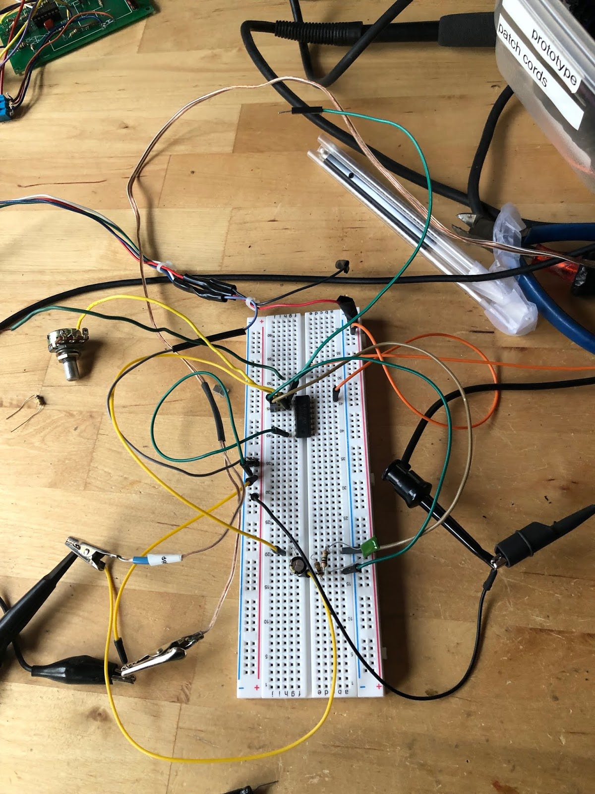
Hours of fun! Experiment with different P/P audio input voltages and DC offsets into a 4069 buffer to hear 50 shades of grunge. You can read more AudioDIwhY posts about DC offsets here and here.


Scope a dope! Purple is original ramp signal from my Siglent 1025 (Siggy plays Guitar) Yellow is the buffered signal at output.  Yes, it inverts....

Wiring up a cap in the feedback loop has some of the same vibe as an op amp active filter:

100K pot is for cutoff frequency....

And running it through more buffers might make the sound gnarlier!


The 4069 punishes that ramp signal!
Try more 4069 inverter stages for a bit more grunge during cutoff sweep. Xtra credit: put 2 of these entire filter fragments in series. Yeh!! 

OK this weekend coming up I will see if I can get this EM 4069UB based LPF to work. I laid out a prototype PCB capturing the design (since I hate breadboarding or stripboarding. If the PCB doesn't work I'll just pitch it). Got it fab'd at my usual spot.

I am wondering how this will work. Hammer feeds positive CV into N channel FETs (5457's); N channel JFETS are opened up by having their gates see voltages below source and drain right?  It's a safe bet the filter works at an elevated DC offset; all the analog 4069 designs I've seen so far do. The key: 4069UB, mind the offset.

UPDATE: I got hammer's Low Pass Filter to work! It sounds good n crazy! Details here.

That's what's fun about analog, you get to ponder these things. Nonetheless, I'll say it again: don't breathe the fumes. See you next time.

WUMP

I came home from my psychiatrist girlfriend's last night and went to bed about 9:15.  
While I was going to sleep I heard, every 10 minutes or so (it was random!) a sort of dull thumping sound, it kinda went WUMP! like someone was banging the side of my house with a stick wrapped in a rag.

I walked around and couldn't see what was making the noise.  

I made sure the front door was all the way shut (it wasn't, which didn't make me feel that good, but it was obvious there was no one else in the house).

I went to sleep but a WUMP, this time maybe a bit more broken stick sounding, woke me up a half hour later. I eventually dozed off again but the noise hit me this time at 11PM.  Now the sound was more frequent at times. WWWUMP! (wummp?)  WUMMMPP!! Mostly it was pretty dull, really sounded like someone banging wood with a stick or something, sometimes with more vigor, and it was really hard to tell where it was coming from.

I cursed but must have fallen asleep again, and by about 1AM a new WUMP, much louder, jolted me again. I was not getting consistent sleep and had a tough work day coming up. I had to do something.

But here was the problem: It was random, sometimes every few minutes, sometimes 4 wumps in a minute, sometimes maybe once every 15 minutes. I abso-frigging lootly could not tell where it was coming from; it sounded like perhaps from outside, from a neighbor's back yard.  Hard to say, but it might have been louder in the back of the house than the front. It would help a lot if it wasn't so damn intermittent!

So I stood in the dead center of my house (I was really, really tired) for 20 painful minutes waiting for the next WUMP so I could track it down. But--of course!--whatever was making the noise refused to cooperate.

So I got dressed and put on boots and found my camping flashlight, stepped outside into the surprisingly warm May 1AM morning  and meticulously went around the outside of my house, looking in crawl spaces, looking around the back of my yard, looking at the trees near my house, seeing if a homeless dude was sleeping in my crawl space, maybe a skunk giving birth under my house or anything else that could make this random WUMP sound. 

WUMP!!!

It actually took a bit of bravery to do this (well I thought it did, anyway) and I was absolutely bone dead zonked out tired at this point but in spite of going over every square foot of my house and yard with a flashlight, probably scaring the hell out of the my neighbors,  I couldn't see anything that could be making this sound.

I went back inside and got back in bed and 15 minutes later heard yet another WUMP!

Back to the dull muffled thump sound. 

DAMMNN!!!

Wait a minute: something on the roof? Seemed unlikely but I hadn't checked that yet!

Before doing the whole go to the garage, get the ladder thing I decided to go upstairs to look through the upper bathroom window at the back roof, then I got very lucky! when I walked by the speakers set up by my bench I heard a WUMP!

I could immediately tell what it was: the computer and DIY audio gear I have in there, which are hooked to some Mackie near fields, were the fault. Everything was powered on, and for some reason (no idea--did I leave some random patch up? Reaktor?  Youtube gone zombie?) the setup was making a random WUMP sound.  It was crazy, and it didn't sound electronic at all! 

The Wump Starts Here!

I shut everything off and it stopped.

And then I could sleep.  That was the end of the random WUMP.

I told this story to my psychiatrist girlfriend the next day and she told me, that's so geeky you should put it on your blog. So, here it is.

CGS blast from the past--Steiner Filter

Hello Again! This time, I repair Ken Stone's take on The Steiner Parker Synthacon filter.

Repaired Filter is working!

The filter design is a classic in the analog synth world, maybe not as famous as the Moog Ladder or Korg's MS20 incarnations, but it's definitely in thetop 40 anyway. Sound demo is here.

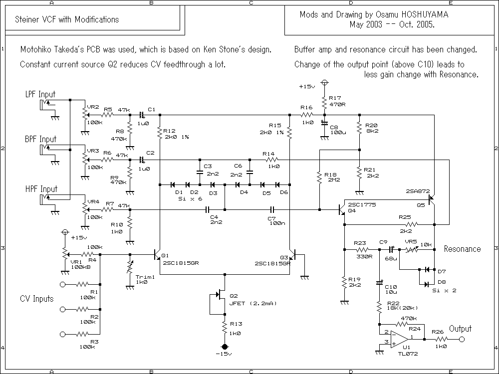
There have been a lot of commercially sold version of this filter: TipTop has one for Euro; Elby has a few incarnations for sale. (Elby took over CGS's site and sales....)  The awesome and insanely productive Osamu Hoshuyama has one w/ variations on his site. It's an unusual design, having LP/BP/HP inputs (not outputs--inputs!) and an odd buzzy harsh sound.

Back in about 2005 I tried out my own CGS build--one of my first attempts at audio DIwhY.  But the filter soon broke--no audio--so I junked it and forgot about it. When I recently found it at the bottom of the junk box I asked around, no one in my Meetup synth nerd group wanted to take a crack at fixing it, so I decided to repair the damn thing myself.

My repair skills have improved somewhat I guess because it was really easy to find the issues. I scoped the BP audio all the way to the output, but there, right by the wire to the output jack, an important trace had lifted, probably during the initial build, and failed. There was enough of the trace left to solder a new wire in place. Now HP and BP work! I found another broken trace near the Low pass input. Easy repaired with a "kludge" or "bodge" wire:

You fix PC's by rebooting. You fix analog audio with kludge wires.


Happy to say it's working again. To my ears Ken's CGS design has the same nasal sound the Synthacon at the local Synthesizer Museum has. OK last thing to do is record it!  Update! Demo done, soundcloud file is here. Have fun!