RP2040/Raspberry Pi Pico Toolchain--Ubuntu, CMAKE, and the Usual Boring Blink Test

 Hello again. I am fully recovered from Covid. It's time to keep marching forward.  

After finishing several projects based on Atmel's 328P MCU (a 328P based complex LFO is here, for instance), it was time to move to a new MCU family--something faster and more powerful. 

Contenders for this next evolutionary step in my AudioDiWHY journey were ST Systems' STM32 MCU's and development  boards--there are a lot of them--and Espressif's ESP32. 


Instead I chose Raspberry Pi's RP2040, the processor found in their PICO development board--mostly because the RP2040 was in stock pretty much everywhere I looked and is extremely affordable.

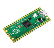
                      

I chose RP2040 because it's the underdog?
                                    

TOOLCHAIN TIME

Here's how I got an RP2040 C/C++ toolchain up and running on Ubuntu 20.04 Linux.

I targeted the Raspberry Pi Pico development board.  It's inexpensive and well documented, and a toolchain that works with the Pico should work with whatever other RP2040-based PCB's I use for future projects. 

For this toolchain I needed software and hardware to write and debug RP2040 firmware (I code in C, mostly), compile the code, and upload the firmware onto the RP2040.  

I recently set up an Ubuntu 20.04 virtual machine running on VMWARE Workstation Pro 16 on a Windows 10 NUC computer (post about my bench setup is here).  I decided to go with this Ubuntu Linux VM for developing on the Pico--I don't use Linux as much at my day job as I'd like, so I'll use it here. 

There are many videos and posts about setting up a Linux RP2040 toolchain. The Shawn Hymel YouTube series here proved useful, as were the posts here and here; and the official PDF here. Also, The PDF for the RP2040 SDK is here.  

My Ubuntu build was "desktop"--that was my starting point....

First I sudo apt-install'd the software I thought I needed:

(from my home directory….)

mkdir pico

cd pico

sudo apt install git  #installs git

git clone -b master https://github.com/raspberrypi/pico-sdk.git

cd pico-sdk

git submodule update --init

sudo apt upgrade

sudo apt install gcc-arm-none-eabi

sudo apt install libstdc++-arm-none-eabi-newlib

sudo apt install build-essential     

sudo apt  install cmake  # version 3.18.4-2ubuntu1 

Can we use RPi's WGET?

To install a RP2040 toolchain on a Raspberry Pi, the RP Foundation provides a wget statement to build the entire toolchain with minimal end user interaction. It's here--go to page 4. 

We are not using a Raspberry Pi, rather Ubuntu, which is very close, so this "gee whiz it's easy!" single script approach might have worked. Or would it?

A common Linux trick is to remove the wget from the command, copy the rest of it into your browser, and see what happens.  

Here it the resulting URL:

https://raw.githubusercontent.com/raspberrypi/pico-setup/master/pico_setup.sh

Following this URL I saw a shell script....fascinating....and begs the question: who is Liam? regardless, I chased down how the script worked and decided it would be safer to build the Ubuntu part of the toolchain "by hand".  

Back to it: To get the system to locate the SDK files for RP2040, I needed to add this via the command line to the Ubuntu PC:

echo 'export PICO_SDK_PATH=$HOME/pico/pico-sdk' | sudo tee -a /etc/profile.d/pico-sdk.sh

To make that command take effect, I rebooted my Linux virtual machine, but I could have run this additional command:

source /etc/profile

With all this in place, I could compile the example sketches found in ~/pico/examples, build from the command line, drag the UF2 file to the PICO, and--we have BLINK! 

We are headed in the right direction. 

OK--next question: what IDE to use? 

I could write the C code using something like VIM (or Pico--different PICO....) but what fun would that be? 

I chose Visual Studio Code, the free (!!) multiplatform, multilanguage IDE from my bestest, smartest, most capitalistic buddies at Microsoft....a kinder gentler Microsoft, the one that no longer misses its meds--is Microsoft finally turning swords into plowshares? 

Nope.

Here are the commands I used install and configure VSCODE, I got these from this webpage.

sudo apt install code #install vscode for Ubuntu

code –install-extension marus25.cortex-debug

code –install-extension ms-vscode.cmake-tools

code –install-extension ms-vscode.cpptools

OK, one of the plug-ins needed for VSCode is CMAKE ("cmake-tools").  What is that?

ENTER CMAKE

It's a high level language--yes! an entire scripting language of its own--used to create Makefiles and perform essential software building/compiling automation.  CMAKE's webpage is here. Think autotools on steriods.

But--I got frustrated quickly with CMAKE. 

Most CMAKE videos and webpages were either geared toward total newbies like me and only discussed basics, like creating a Makefile for a single "hello world.c" file, or were extremely, and I mean extremely, complicated.

For software development shops, needing to compile, test and deploy complex software, CMAKE can do everything--however, CMAKE might be overkill for DIY folks trying to blink LEDs?  

In my case CMAKE kept throwing errors. It couldn't find the Pico SDK.  This should be easy!

I wasted over 3 hours trying to get this to work. 

To get to the bottom of this frustrating issue, I ended up buying a CMAKE book on Amazon (the book I got is the one here). 

With that in hand, I figured out the issue (see the "export source" statement above, that alone shoul have worked, but didn't, and the export $PATH statement provided by RP foundation didn't work for me--nor did tweaking path variables in VSCODE).

I am still not sure what caused the issue, or what fixed it, exactly--this should have been a really easy fix; it's just an export statement, but for some reason it wouldn't work for a very long time, then started working for reasons unknown.

Whatever--there is a whole career scripting CMAKE, right?  To learn more, the original CMAKE guy talks about his whole enchilada, here

Monkey CMAKE, Monkey C-DO 

CMAKE requires a single script in the project's root to work--called CMakeLists.txt.  No, you can't rename this file. No, you can't move it to some other folder. 

Here is the CMakeLists.txt I got to work for a blinkcl.c test program, which, well, blinks a damn LED. 

######

cmake_minimum_required(VERSION 3.13)

#include the cmake build functions from pico SDK

include(pico_sdk_import.cmake)

#project name and code here

project(BLINKCL C CXX ASM)

set(CMAKE_C_STANDARD 11)

set(CMAKE_CXX_STANDARD 17)

#bring in this function to add cmake Pico SDK functionality to build

pico_sdk_init()

#list out files used

add_executable(${PROJECT_NAME}

blinkcl.c add.c

)

#create extra uf2 etc files to copy to PICO via USB

pico_add_extra_outputs(${PROJECT_NAME})

#linker needs to use these libraries

target_link_libraries(${PROJECT_NAME} 

    pico_stdlib

)

###################

You may want to change the project name ("BLINKCL") and filenames ("blinkcl.c", "add.c") if you want to use the CMakeLists.txt files below as a basis for your own projects. 

And! One more thing--you don't need to list out .h files in CMakeLists.txt if they are in the same directory as your .c files.  

 I also copied the pico_sdk_import.cmake file into the root directory of my project ("BLINKCL").  This appears to be an include file (not sure that is the right term) that helps CMAKE find the Pico SDK.

For uploading files to the RP2040, I put the pico downstream from a USB hub with a power switch--you copy firmware onto a PICO by copying a UF2 formatted file from Ubuntu to the PICO, but copying these over requires holding down a button on the PICO while plugging in the USB cable.   

The switch on the USB hub makes that process much easier: hold down the white button on the PICO and flip the switch on the hub....


Blink me up, Scotty? 

My goal was to have 2 .c files, one .h file and everything else needed to build a multifile blink project.  

Here's the code:

#################################

#blinkcl.c

#include "pico/stdlib.h"

#include "add.h"

int main() {


    uint16_t time;

    time = add2nums(100,100);

    const uint LED_PIN = PICO_DEFAULT_LED_PIN;

    gpio_init(LED_PIN);

    gpio_set_dir(LED_PIN, GPIO_OUT);

    while (true) {

        gpio_put(LED_PIN, 1);

        sleep_ms(time);

        gpio_put(LED_PIN, 0);

        sleep_ms(100);

    }


}

#############################

#add.c

#include "add.h"


uint16_t add2nums(uint16_t a, uint16_t b) {

   uint16_t x = (a + b);

   return x;

}

#############################
#add.h

#ifndef ADDCH
#define ADDCH

#include <stdint.h>
uint16_t add2nums(uint16_t a, uint16_t b);

#endif

#############################

I built the firmware from these files without having to leave VSCODE.  

Yes the add.h file, the add2nums function, etc. are not needed, but I wanted to make sure the toolchain could deal with multiple .h and .c files. Yes, it could.

A tip, mentioned everywhere online when CMAKE is being discussed: if I altered my CMakeLists.txt file, I had to delete the entire build directory in my BLINKCL project folder then build the software again. Yes, I saw this, over and over.  

Last thing I did was get USB serial working for simple debugging.  I wanted to know the value of variable x?  

printf("x is: %d",x); 

This is very basic debugging.  

It turned out to be pretty easy.  I had to add this to the bottom of the CMakeLists.txt, rename the project, and rename .c files used:

#control USB output--1 means on.

pico_enable_stdio_usb(${PROJECT_NAME} 1)

pico_enable_stdio_uart(${PROJECT_NAME} 0)

Then I used this bash script from terminal to get minicom going.  

#!/bin/bash 

sudo minicom -b 115200 -o -D /dev/ttyACM0

I then wrote a simple hello.c project to printf "hello" 1000 times. It's very similar to the Pico example for "hello world".  I am omitting the actual code I used for this last test, but if anyone is interested, comment below, I can provide it.

I built it, and copied the UF2 file to the Pico.

The ascii output went out of the PICO, into the VM, and showed up in Minicom on the Ubuntu VM.

Joy!

Serial Ports--RP2 as a removable device on an Ubuntu VM--Why don't they work consistently?

As mentioned, my toolchain uses an Ubuntu virtual machine running on a Windows 10 PC.  The hypervisor for virtualization is VMware Workstation Pro 16.  A feature that caught my eye is what VMWare calls "USB passthrough"; I figured I'd need that since the RP2040 toolchain relies on the ubuntu VM reaching the Dev board via USB.

However, I quickly found that USB passthrough didn't always--pass through.

I had issues after the initial setup--the USB port used by the Pico/RP2040 was occasionally invisible to the Virtual Machine. Less frequently I lost the ability to see the pico dev board as a storage device, so i couldn't drag UF2 files to it.

Best I could tell this was because the PICO device was recognized as a plug and play serial device by Windows 10, which disallowed the device to be visible on the Virtual machine. So--in spite of my attempts to have USB "pass through" the W10 host, it--didn't.

Of course I messed with various settings as per the page here. No help.

To fix this, first I powered down the Ubuntu virtual machine.

Next, I went to device manager in Windows, checked "showed hidden devices", right clicked on the PICO device under "serial ports", left clicked on "uninstalled device" (I didn't uninstall drivers, just the device)

I then unplugged and plugged in the PICO to Windows 10 USB cable. 

The first time the PICO came back, and was visible again via Device Manager. Again this robbed it from being visible to the VM! But after doing this procedure twice, it appeared to be gone again.

After that, powering up the VM, I could see /dev/ttyACM0, drop UF2 files on the PICO, and so on. I was back in business.

Update: the problem is back. 

I blew away hours and hours today trying to understand how this works, so i could hope to get a final fix, but had little success. After several hours it started working again...not sure why.

What I think:

To make the serial transmissions "work as a USB storage device" on Windows 10, you really can just plug 'em in. I tried it on a W10 laptop--yes, it is plug and play.

However, to make the same features work on an Ubuntu VM, I had to get rid of all traces of "the RP2040 dev board talking to Windows". I used Windows device manager for this. I right click and uninstalled anything that looked Pico-ish: "RP2", "RP2 boot", "Pico", "PicoProbe" and so on.  

Once again this fixed it--for now.

As a baseline, here's a look at Windows 10 device manager when a Pico Dev Board is working as a storage device and "pass through" is working:


And here is it when it's actively sending serial data over USB (so, a correctly crafted printf statement, a correct CMakeLists.txt file; a successfully uploaded UF2 file)--the enabled USB serial device "moves up one":


The correct driver for these "VMware USB Devices"--and the only one that seems to work--is this one. 


A reboot of the Windows 10 host was needed when changing drivers....

Because the PICO could mount on the Windows machine or VM, it queried me to ask my choice--on which which device do I want the USB to be visible? I was tempted to say "always mount the Pico on the Ubuntu VM" when asked, but after wasting hours trying to get to the bottom of this issue, I changed my mind. Let it ask me each time.

Have I seen the last of this? I figure not. Until i know more about why this keeps breaking, it will keep breaking. 

Frustrating! There is a real lack of information online about how any of this really works--at a deep level--mostly I can find: forW10 just plug it in--it works; the drivers are included; and for vmware workstation pro--just plug it in--it works--the drivers are included. Uh huh. By magic, right?

Some basic considerations before I shelve this for now:
  • The serial port won't work (and minicom will close immediately) if there is no UF2 file loaded on the dev board.
  • Same if the printf or whatever is generating serial data is incorrectly crafted in code--just because it compiles doesn't mean it will work.
Update 6-22-22.  More digging into this--still having issues, especially with serial data over USB-- being able to see RP2040 USB serial content on the Ubuntu VM is still not working reliably.

 By using various tools perhaps I see what's going on here:
  • I upload a USB serial UF2 on the RP2040 dev board--it has a printf() statement for instance. 
  • this sends "hello world" or whatever out the USB port for a computer to display via a terminal program.
  • The Windows machine sees new USB serial traffic
  • An interrupt is sent to the Windows OS (?? How does this really work? I paid for a support ticket at VMware, to have them explain--but the tech seemed unwilling or unable do that beyond pointing me to the documents I've already linked in this post. If I get time, I may dig into this more and try to reverse engineer vmware "USB passthrough" technology, to better understand it, beyond the dreaded "plug it in and it just works" excuse) 
  • I choose "USB needs to appear on the VM" from the VMware USB passthrough UI.
  • Windows puts a VMware USB driver on the newly found port (?), giving up control of it.
  • ttyASM0 is created on Ubuntu, hopefully.  This is the /dev file created when Ubuntu sees a CDC USB device, which apparently is what the passed through USB is.
  • I load up minicom and can (on a good day) see the serial output via /dev/ttyASM0.
OK, and when it all works it's great, but the whole process, from rebooting the RP2040 dev board to being able to see serial output via Ubuntu minicom can take a lot of time--from a few seconds to over a minute.  

In the meantime, the serial traffic may have already have gone by!

Therefore, I have given up on using USB serial on the Ubuntu VM. 

Instead I wired TX, RX, GND from pins 0, 1 and 2 on the PICO dev board to 14 and 15 along with ground on a headless Raspberry Pi 4 on my bench. I had to change some settings on the Rpi--see the video here and webpage here--to make incoming serial work. Not difficult.

I also found that the serial data can be found on /dev/ttyAMA0 on the Raspberry pi 4 when it's working.

I ran a ground wire between GND pins on both devices. You get scrambled eggs for STDOUT if you don't do this.

In CMakeLists.txt, i selected "Serial not USB" and recompiled:

#control USB output--1 means on.
pico_enable_stdio_usb(${PROJECT_NAME} 0)
pico_enable_stdio_uart(${PROJECT_NAME} 1)

next I ssh'd into the RPi host and ran minicom (actually, I created the bash script below:

#!/bin/bash
# basic config settings to have USB to serial in Ubuntu minicom 
sudo minicom -b 115200 -o -D /dev/ttyAMA0

Then chmodded it:

~chmod 777 ./minicom.bash

Now I can run it:

~./minicom.bash

Works!


No more delays--no more hassles with USB-> serial password not working some of the time.

I can leave the RPi Minicom terminal program up and running all the time and send it data using things like printf() or puts().  

No issues so far.....Whatever comes down the wire is almost instantaneously seen on the RPi4.  Seems perfect!

"Dr! Dr! It hurts when I stand up!"
"Well don't stand up!"

This could be cleaned up....maybe a breakout board for UART is needed, with LEDs for TX and RX activity? I already fabricated a better looking serial cable.  That might be good enough.


Outro: RP well and Live 

Next time assuming I can see the damn dev board at all, I will be setting up more complex debugging, then on to some real audio projects.  Update: hardware debugger works. post is here.

The debugger PCB is off to PCBWAY, my faithful sponsor, and they are always good about getting the PCBs back quick. So: more posts soon. See ya next time.


Virgule/emulsiV: Learning RISC-V Assembly Language

 I finally took a long vacation with my psychiatrist girlfriend. We flew to Portugal--from the USA--10 1/2 hour flight. Super Fun! 

Of course we ignored the COVID-19 warnings like this one

Bad news--when we were leaving, she tested negative for COVID-19, but I didn't, so she left, and I was stuck.  

I self-isolated in a hotel--six days, although the Portuguese health authority said it would be more like 11 days--to do what? 

Ignore the shelter in place mandate and go to museums?  No. Getting the locals sick--I found them calm, polite, and often downright zen--not my thing.

Ignore the mandate and go to the beach?  Nope. See above.

Ignore the mandate and ride the ridiculously crowded tram 28?  I wouldn't do that if I was healthy, so, no.

Learn some new programming skills, of course. RISC-V assembly!! 

RISC-V based dev board from Sparkfun
 
WELL ARMED?

I've already written posts about assembly for the 6502 processor (here) and ARM (here). 

With 6502 it was pretty easy to learn assembly language basics; ARM, not so much.

Another instruction set architecture ("ISA") is RISC-V; it's open source and was designed to help teach newbies like me how processors work. 

I expect RISC-V to become increasing popular as chip makers become weary of giving ARM and Intel bags of money since RISC-V has no license fee.  

So, here I was, stuck in Lisbon, Portugal, alone in a hotel room, only me and my ancient MacBook Pro. Can I learn a new ISA without going crazy?  

Yes. I found an amazing online simulator for learning RISC-V--"Virgule" (a simulated RISC-V processor) with "emulsiV" (an emulsifier for Virgule? No idea what the hell emulsiV means)--find them here.


Documentation for Virgule/emulsiV is a bit sparse, but I could follow it--which means you can too--it's here

A good RISC-V/Virgule introduction video--short and informative--is here. As the video correctly notes: Someone put a lot of work into this simulator. This must have been a scripting project of passion, and it's one of the best, and at the same time simplest, online simulator I've seen to date. Viva la France! 

It has an ASCII display, behind glass GPIO, about 2-3k of simulated RAM and even a memory location where you can load and view bitmap images. 

It gets better: You can animate what happens inside Virgule/emulsiV as you step through your code, and control the speed of the animation. Not only can you see if your code works, you can see how it works at a snail's pace.. This greatly helped me understand RISC-V at a deep level while writing, debugging, and running my code.

There are different ways to get code into the simulator; for me, I hand-coded instructions into the memory column on the left side of the simulator, then stepped through my code to watch it work. 

If I made a really dumb data entry mistake the simulator tried to correct it and did a remarkably good job. Amazing! As a learning tool, this couldn't be more straightforward.

Enter assembly code right into memory slots....


REGISTERS: 

The simulator has 32 general purpose registers.  RISC-V's spec indicates that hardware does not have a central accumulator and that register x0 is always 0.  

Programmatically we call these registers x0 x1 etc....this is not hex, which is denoted 0x000 in the simulator as you'd expect; the registers are called out via decimal with a preceeding "x".  

The documentation talks about RS1, RS2 etc.--these are considered SOURCE registers; also rd1, rd2 etc, these are the DESTINATION registers. 

Other than x0, any register can be used as a source or destination.  


IMMEDIATE VALUES

In the RISC-V ISA, immediate values ("IMM's") don't seem to have the odd rules, complexities, and head scratching limitations that I found in the ARM ISA. 

 An easy way, I think, to get immediate values into registers is to use addi instruction—"add immediate":

 Addi dest, source, value

Source can be an existing register with a value stored in it….this next instruction puts 32 in x1, and register x0 can only have 0 as its value: 

addi x1, x0, 32

However, For some instructions, like lui, Immediate values are entered like this

0xyyyyy000

where  yyyyy is a 32 bit hex value. So the LUI instruction is a good way to put a large immediate value into a register:

 lui x2, 0xc0000000  ;put c0000000 hex in reg 2

But what about the 3 LSBs, they never get can a value?

Ha!—use addi after a lui—a trick!

addi x1, x0, 32

In this instruction: x1 is destination register;  x0 is source register and has value of 0, and 32 is the value to put into the LSB's

STORING VALUES

Virgule emulates a 32 bit RISC-V processor, so  you can store bytes ("SB"),  half words/16 bits ("SH"), or words--32 bits ("SW"). 

The general instruction for storing a byte (bits 0:7) is this:

SB (what to store) (where to store) 

so---

SB x1, 0{x2)

SB means take 0:7 bits of what to store--in this case the value in register x1, and copy it to register x2, offset by IMM 0; in other words, copy the value in register x1 to register x2.

And--you can store to memory (as opposed to a register) using an offset value greater than 0—see the "Extra Ram" section below.

LOADING VALUES

Works the same way as storing but going the other direction.  

LB x3, 0(x2). 

Loads a byte to register x3--the value found in register x2. 

If the offset is 1 or greater, you are loading bits 0:7 from a memory cell, not a register.

EXTRA RAM

Not  well documented, but you can store and load values to and from virtual RAM, not just in the 32 registers provided.

For instance:

SB x5 1(x1) 

stores bits 0:7 found in source register x5 into a virtual a memory slot--in this case 1 added to the memory location previously stored into register x1. 

If x1 contains zero, and the offset is a 1, you are storing a byte into memory location 1.

Remember that x1 already contains a value, to which an offsite is applied.  So if x1 already contains the value 3,  SB x5 1(x1) will copy bits 0:7 of  register x5 into memory cell 3 + 1, or virtual memory cell 4. 

As far as how much "extra RAM" we can use in Virgule: As far as I could tell, I had 1-2047 memory locations to offset from (x1), but when I went outside that range things didn't work the way I wanted.  

However the memory map indicates 0-3071, more like 3K locations rather than 2K, including x0-x32 used as registers, but I couldn’t make things work with offset values  >  2047.

It would be great if someone could show me exactly how all the memory 000 to CFF is mapped--because I am missing something here and didn't have time to fully figure it out. 

Comments?  

Unfortunately the sim does not have a way to display what is in this extra virtual RAM. Only register values are shown.

WRITING ASCII TO THE (fake) ASCII DISPLAY

Output from Virgule's virtual ASCII display.  Get the hex code, ready to load into Virgule, here.

Here's one way to do this...

lui x2, 0xc0000000  ;put c0000000 hex in reg 2

addi x1, x0, 75. ;put 75 in reg 1

sb x1, 0(x2) ;store value at x1 (75 is ascii letter “K”) to the simulated text display

IMPORTANT! always make your code use offset 0 above.....I assumed to make the cursor appear at the next spot to the right, use offset 1, and for the next, use offset 2, etc. but that crashed the simulator.

The simulator will automatically increment the cursor to the next available slot the next time you do an ascii write. Just keep writing to the ascii display over and over--this is not well documented, but you can figure this out from the examples.

WRITING TO THE FAKE LEDs

GPIO's! Of course this simulator has them. Virgule has an impressive array of virtual LEDs, switches, and push buttons. They can be configured by right clicking on one of the GPIO points and choosing what you want (impressive by itself!). You need to set the direction (read vs. write) using an SB instruction, then use subsequent instructions to do other things.

I wrote some simple code to light the first row of LEDS:

we put the memory location for our GPIO into reg x1

lui x1, 0xd0000000 ; memory location for virtual GPIO

sb x0, 0(x1) ; this makes the LEDs outputs  

addi x3, x3, 126. ; put 126 into x3 (it can be anything from 1 to 255)

sb x3, 16(x1)

Final instruction writes what is in x3 to x1 offset by 16.....16 is the memory location for VAL, the values you want to write to the GPIO "pin".

JUMPS

These instructions sounded intimidating after watching videos and online reading, but after experimenting, they are not too difficult:

JAL: jump the program counter to immediate value; then put the count of the next program counter instruction to run, after the jump has occurred, into a register. 

let's look at the instruction

jal x1, +24   

So! If Jal x1, 24 is put into instruction "memory" position 00, the program counter jumps to PC 18 (24/4 is 6, you are jumping the program counter forward by 6 instruction memory “slots”); then, Virgule puts 1c into register X1 since 1c is next PC slot after 18.

JALR; register and offset contain where to jump to.

Jalr: x3, x2, 0

x3 stores the next program counter “slot” that would have occurred if the jump didn’t happen.  X2 is the value of where to jump to, offset by value 0.

ENCODING

If you want to understand RISC-V at its deepest level, check out how assembly is turned into the 32 bit values hex values  sent to the processor. 

Understanding encoding would be critical if you are writing a compiler, pulling apart RISC-V hex instructions using C, and so on.  A detailed video (long, deep, and quite informative) covering RISC-V encoding is here.

THE WHOLE J, S, R, U thing: RISC-V in its 32 bit form expects all its opcodes, functions, values, etc, to fit into 32 bit words. The opcode is always in bits 6:0.  But from there it varies how the opcode, values, register/memory locations etc, are encoded. In the RISC-V spec, there are a few different “formats” used, with letters like J, S, R, U to designate how this it's done; in other words, each letter designates how a given 32 bit word is encoded

Encoding instructions: I assumed for everything RISC-V the opcode contained the instruction itself. "When you assume" right? 

Um, no. In some cases the opcode alone isn’t enough. Instead, an instruction's opcode (bits 0:6) can be a general marching order, while one or two “functions” further define what needs to be done during decode step. They are called “function 3” and “function 7”. You knew that right?

For instance, for ADDI, opcode is OP-IMM. And function is “ADDI”.  

However, for the LUI instruction, the opcode itself tells the CPU's decoder everything it needs. You knew this as well?

Encoding Register values: to try to better understand this, I dug into how a 32 bit RISC-V instruction knows what registers we want to use for an instruction. 

Turns out RISC-V, in its 32 bit version, uses 5 bits for register values. Hello?  That should allow for 2 raised to the 5 registers or 32.   

So, how does the system encode the value 0xC000000 to register x30?  and not send it to x7 by mistake? 

Here is how: mask everything else in the 32 bit word, that, by the aforementioned letter designation, does not represent a register, then turn the 5 bits left into a decimal number. For instance you have an RD of 0 0 1 0 1 that means we want to use register x5.

The entire encoding process, turning commands into bytes, opcodes + functions into instructions, numbers into signed or unsigned numbers, etc., is a bit complex, but like all things RISC-V--it's manageable if you put a bit of time into digging deeper. 

Overall I figure RISC-V is what happens when friendly, helpful, well meaning college professors and grad students--as opposed to apathetic/screw-you-I'm-tenured/screw-you-again-I'm-a-certifiably-bonkers-T.A./I-give-not-a-poop-about-you-wanting-to-learn-things-I'm-too-busy-bedding-coeds/I'm-busy-boozing-and-making-my-research-paper-deadline-so-don't-bug-me basket case profs I had back in my college days--um, when they create a cool ISA for pimply faced freshmen.  

COVID CODA  

I will spare you the puns of RISCing things by traveling abroad...too late.

Experimenting with RISC-V using this simulator helped me keep my limited sanity during the days I was locked in a hotel room, waiting for the Portuguese government to let me back on the plane. I have to say that for a vacation with a big bummer ending, this RISC part of the trip was fun! 

RISC-V is a blast to code as I see it--it's fun, interesting, and for those wanting to try something new that's even legal: highly recommended.

In the future I might create some RISC-V based projects and get my sponsors PCBWAY (had to get a plug in right?) to help with the fab. Stay tuned.

In the meantime: there are code examples included in Virgule but some of them seemed a bit complex to me, so I wrote some of my own code, attempting to make things as simple as possible. 

My trail of breadcrumbs? Sure. You can get my code examples, in hex, ready to load into Virgule/emulsiV, with a brief readme about what does what.  

Go to my github--here.

As far as COVID-19: turns out I was lucky and my symptoms were mild. In six days I got a doctors note and was back on the plane to the good old USA. Now I am happily blogging, and the weather here is fantastic. 

COVID-19! It's what you get when you breathe the fumes.  I would not feel so all alone...Keep coding, jester. 


Tube Timbre Trasher, Not Done, But It Works

DiWhy QUESTION! why start building something that you don't completely finish? 

Answer: Because you can!!

it works!

This time I used two 1J24B low voltage pentodes, a tube I first learned about from Ken Stone's tube VCA, to create a timbre modifier. The result is a "waveform folder" common to the West Coast synthesizer sound.  Two 1J24B pentodes a few op amps and caps are almost all you need.

You may want to read previous posts here (introduction to 1J24B), here (experimenter PCB for this concept), and here (the 2x tube breakout board) before running with this project. 

We begin with 3 PCBs from my generous and always enthusiastic sponsor PCBway, check them out here

Clockwise from the right: primary signal processing and conditioning, a dual tube breakout board, and I/O like jacks and pots.

First I built up the 2x tube breakout board:


Then on the the main PCB. 

There was a trace error in the main main PCB, which is fixed in the project's post at github (here). I was sending too much current through D1 and D2 on the dual pentode breakout board and I kept blowing up the diodes. Took me a while to figure that one out, but I got it sorted.

Bodges R Us! Can you spot the trace fix?

Otherwise, other than calibrating the 2 trimmers, it worked first time. It was tricky to set it up. 

If I over-biased the CV's and audio signals it distorted the incoming signal so much that I ended up getting nothing at the output except an op amp slammed against its supply rail.  

Best way to calibrate: put a 0-5V triangle wave the CV input and a 10V ramp audio in then look at the corresponding testpoints with a scope. Turn the CV and audio input pots full up. You should see the grid signal modulating from about -1V to about -6 and the screen between about +12 and +15V.  If not, you may have a mistake somewhere, trace the signal to figure it out....If the incoming signals are making it to the tubes, put a 10V ramp signal at audio input use a 0 to 5 control voltage at CV in.  Adjust the trimpots until it sounds the way you want. The CV trim will have to be adjusted a fair amount, but you will hear the modulation effect come and go when you start to hit the sweet spot.


Overall this design is not finished--I never fabricated a front panel for it, for instance, but as it is, it's OK. For the complexity of this design, it makes more sense to use a simpler approach, perhaps use a Norton 3900 instead of 2 tubes--the two different approaches sound very similar at in terms of how they fold a ramp wave.  


You can hear what the Tube Trasher sounds like here.  I intentionally made the audio clip simple, just a single ramp or triangle audio wave modulated by a single VCO, into my DAW. No effects, no other modules....we hear a 10V P/P ramp, sine triangle from a VCO, modulated by a 0-5v triangle CV from an LFO Prime. 

For normal audio (say, vocals, a string section, a Solina, whatever) the distortion you end up with sounds pretty--well, really, bad. I didn't bother recording that....

And of course as per this sad post, 1J24B's are hard to get right now, and maybe will from here on, due to world politics. 

Power used for the prototype is +/- 15V, 20mA for V+, 40mA for V-.

For euro fans, aka doepfer smokers: the design works with +/- 12V power but I had to recalibrate the trimpots. I got it to work to +/- 10V as well.

If anyone wants to improve and refine this tube based wave folder, have at it, but for me it's time to move on. 

thanks to PCBWay for their support and encouragement while I was building the Tube timbre trasher. 

So what could be next?  

  • The tubes can be flipped 180 degrees to not stick off the side of the main PCB. I put the tubes off the side as you see above to help with design and troubleshooting, but flipping them to be less obtrusive is trivial--mount the BOB with 90 degree edge connectors on the other side of the main PCB.  
  • You may want to 3D print something to fit between the board and the tubes, and drill some holes to tie wrap the tubes down. As it is, they are pretty fragile.
  • I think building a VCA or some sort of high-gain amplification device ahead of the trasher would be beneficial to its performance.  Things sound pretty good with very hot input waveforms, say 15V P/P vs. 10V. The incoming amplitude at input very much influences the wave folding you hear at output.
  • Can this fold "normal audio" vs. waveforms? It should be able to. What would it take to do that? I  think I'd have to redesign the way the audio inputs are biased, which might be a lot of work.
  • What does a quad version of this sound like, or 2 of these 2x tube designs in parallel? I was pretty excited about this design at first, but lost a lot of steam when 1J24Bs got hard to acquire due to the war in the Ukraine. That alone, at least for now, makes me not want to work on this project too much more; it is so sad..... 

After all that encouragement: Get all the gerbers, pdfs, BOMs, wiring guides, etc., at my github here. Nevermind the spooning--I encourage forkers.

Onwards: It's time to conjure a new C/C++ toolchain and MCU for the next batch of projects. I am thinking RP2040 or STM32, both popular, inexpensive, and fast, and each more capable (albeit complex) than the beloved Atmel 328.  

I won't be posting as much in the next few weeks while I experiment with toolkits and these processors. Oh and return to my day job after 2+ years under pandemic house arrest. After that, I'll be back with a vengeance. Stay tuned.

124B Pentode Dual Tube Breakout Board. Not a fun Post.


Sad to say that AudioDiWHY has not been fun over the last few weeks. A pervasive sadness has crept in and my pychiastrist girlfriend says I need a break.

I finished working on the tube timbre trasher (part one here).....where I am designing and prototyping a synthesizer waveform distortion module using a Soviet-era low voltage pentode, the 1J24B. For this post, let's focus on the breakout board needed for the prototype. I'll post the rest in a few days.

Tube audio! Fun stuff right? The Soviets—they knew tubes!! Long gone and good riddance?  Let’s take some tiny, low voltage tubes used in USSR fighter jets, turn swords into plowshares, and use them for audio! 

Until….until....when cleaning out my lab, I mindlessly dug up the box the 1J24B's came in:


I redacted the Ukrainian vendor's name and address, but after searching the web, as far as I could tell, the Ukraine was the primary source of the worlds' NOS, affordable 1J24B's

Needless to say these parts, which were really easy to obtain 2 months ago, are no longer available on Ebay, and perhaps anywhere else, due to heartbreaking world events.  

Specifically, the 1J24B's I had been using for my prototypes came from the same Ukrainian city you see in the war correspondence here

The news from this part of the world is maddening, confusing, and at times, terrifying. My psychiatrist girlfriend, usually tough as nails, was about as scared and upset at the news of the conflict as I've ever seen. The battle at Zaporizhzhia made her frightened for her kid, who is studying abroad, not too far away from the conflict, as well as for herself, for the world, and for me. 

This made me want to stop working on this for-fun project and spend my time doing more useful and constructive things. But I am still stuck at home due to the global pandemic, and found myself continuing to work with my remaining 1J24B's.


Anyway....putting politics and emotions temporarily aside, well before I realized where I sourced the parts from, I created a two tube version of the 1J24B breakout board you see in previous posts here and here. I posted the files for this board on my faithful sponsor, PCBWAY's project page, here. 

The design requires you have some 1J24B’s already or can get some.

UPDATE: 5-25-23 Tragically: the war in Ukraine drags on, but these tubes are available again from Western retailers. Synthcube for instance has them in stock as of today it appears: go here.

If so, you can use this PCB to breadboard a low cost, low voltage dual tube design, say a push pull amplifier or a tube based op amp. 


Cathodes for this BOB require ground and -2 to -15VDC. See the post here for how the 1.5V direct cathode power works.


Under different circumstances, I’d be all over further experimentation; finding audio uses for these extremely interesting tubes would be a lot of fun.


Now, not so much. Due to the war, it's not much fun experimenting with these parts.  Maybe it's just me.

Damn. 


Differential Op Amps--Analog Math Fun! Simple Curve Tracer!

The folks at the incredible Bell Labs were on fire right?  

I see that the C programming language came from those guys, along with the transistor.  

They were pioneers in electronic music creation, even.  

But, arguably, we audio DIWHY folks' favorite Bell Labs creation is the op amp--the handy 25cent  IC commonly used in a negative feedback loop for analog data processing.

Yes, Bell labs invented that as well.  


Op amps are everywhere! I use them everywhere in my designs....so does everyone else--adding two signals, changing a DC offset, inverting an audio signal, as a comparator.... 

Question: Can we use it for simple subtraction? 

Of course. It's easy.


Simple math fun: subtract two voltages--if R1 = R2 = R3 = R4, the output is V2 - V1.  


By setting R1 = R4 and R2 = R3, you can gain up V2 - V1; the relationship of R2-R3/R1-R4 gives you your gain.


You can add more inputs and do more math, but it starts to get a bit more complex fast (Hope I got that equation on the right, right?)


So what else can we use the difference amp for?  How about a very simple mic preamp (here)? 

Can we use a differential op amp in test equipment, to measure the voltage drop across a shunt resistor ? Yes.


Indeed. This is an extremely common circuit fragment in audio--you can find a differencial op amp in the output stage of YuSynth's popular VCA design, for instance:


Pun Intended 

I took a "different" approach; I wondered if I could use a difference op amp to form a basic V-I component tracer (a good video about how to build a simple tracer--without op amps--is here).  

To motorize this pursuit, I could have breadboarded a $2 curve tracer, but I hate breadboards. Instead, I crafted a very simple differential op amp PCB and sent the gerber off to my sponsor: PCBWAYHere we go again with the shameless plug: Help out this blog and check 'em out OK?


The board came back to the USA really fast....here it is.


Populating it took about 30 seconds....give or take.....


Ready to hook up +/- 15V and ground and start testing things....


To trace a diode I put a 100hz 10V P/P triangle wave from a Siglent 1025 waveform generator into "FG-in"; put a diode under test between TEST1 and TEST2 wirepads, soldered a 1K resistor into R4, and jumpered R1. 

Next I tied IN1 to J1 and In2 to J2 (or IN1 to J2/In2 to J1, depending on how I wanted my scope trace to appear along the X axis--both work). 

I increased the gain of the circuit by increasing R2 and R3 to 10K. This made the range of the traces easier to see on my scope. 

To wire the PCB to my scope (a Siglent 1202XE--for X-Y mode, press the "acquire" key and then using the soft buttons below the display, set "XY"  to "on") I ran the FG-IN signal to Y input terminal and the output of the op amp to the X input terminal.


Some meatballs with my spaghetti?


For a diode--the result is a quasi-decent curve:

4004 diode....

5V zener....

The problem I faced: op amp rails max out at maybe +/-15 or 20V, but for a useful trace cursor, I needed a much wider voltage range, maybe +/- 60V, which would fry any ordinary op amp.  This single differential op amp design cannot accommodate the high voltages needed to create traces for parts like the one here. Oh well.  

I also needed a staircase generator to generate traces for transistors (example schematic can be found here, but I'd probably use an Atmel 328 MCU and a MCP4911 Digital to Analog converter instead) , as well as a switch or relay to compare the curves of 2 different transistors under test. 

Maybe in the coming months I'll work on this.....

Anyway if you are a fellow breadboard hater and would rather get this very simple differential op amp configuration on a thru-hole PCB, you can get the gerber, Eagle files, BOMs, PDF's etc. from PCBWAY's project page, here.

Coda 

I am curious: what happened to Bell Labs?  They got sold to Nokia. I didn't know that--you learn something every day. So much for American Ingenuity right? The trust busters broke up Bell in 1984, so the biggest monopoly we're left with are these guys.  Has Nokia made the transistor obsolete? Come up with a more popular programming language than C? Not yet. But! They have given the planet a ubiquitous ring tone

Al Fine 

In the immortal words of the Chambers Brothers: Time! Time to start wearing real shoes again. Time to shave every morning....time to go back to my 1.5+ hours a day work commute--after two years--wow.  

It was real, it was fun, but it wasn't real fun.

Sequential Quad Sample/Hold

I've not had time to post to this blog lately; COVID stats are improving here in the Northwest US, and thus I am commuting to my day job again. 

This is good news I guess--the "health is improving" aspect, anyway? 

During the (hopefully) final few weeks of our collective two year COVID house arrest I found myself digging through my box of old audio IC's: which puzzle to solve next?  

The Curtis ElectroMusic System's CEM3394, intrigued me: an "all in one" synthesizer chip used in the Sequential Multitrak, an instrument I owned and loved back in the late 90's.

I don't know what happened to the Multitrak.....I sold it? Loaned it? Couldn't remember.....


I had four new old stock CEM3394's in my junk box. Could I make a single board, low parts count synth out of these IC's? 

Where would I start?

Like the popular CEM3340 IC, the CEM3394 required analog control voltages to function. I wanted to understand how the internal control voltages ("CV's") were implemented in early digital/analog synthesizers--and use that in a future 3394 project--since I wanted to stay true to the spirit of these venerable old designs.

I'd need a to pick an MCU for the project--the 3394 chips were designed to be microprocessor controlled. Some old synths used Z-80's, but would an Atmel328 work?

I started to research and came across this post. Short answer: yes, this could work!

(Aside: The post's final comment from "Grumpy Mike" makes me sad, it's the kind of fear and loathing and BS I really dislike; besides, he's wrong. Sequential CEM based gear from that era didn't use 16 or whatever DACs in a single synth, and when they worked correctly had internal CV's that didn't sag--you could hold a single chord for hours and it was solid). 

How did Sequential avoid putting several (expensive) digital to analog converters ("DACs") in every instrument? And how did they keep critical MCU controlled CV's, like oscillator V/octave, rock solid?

Turns out they used multiplexers, or MUX's (for the Prophet 5, CD4051 IC's) and had a Z-80 processor refresh a DAC that in turn fed many MUX'd sample and hold capacitor + op amps circuit fragments, quickly, over and over--sequentially.

That way the SH's outputs would not droop, and very few MCU and DAC's--relatively expensive components then and now--I see just one of each in the Prophet 5, right?--were needed for a complete, complex microprocessor controlled analog synth. 

Prophet-5--thing of beauty!

No Holds Barred

The Prophet-5's service manual helped me understand Sequential's no-droop sample and hold. Get its PDF here; an excellent explanation of how the MPU > DAC > S/H mux's work is on page 29.

But!! As a curious DiWHY dude, why read when you can build? 

I designed and laid out a simple quad sample and hold board, which I called, predictably, "Sequential Quad SH". 

Coded it--built it.

Worked first time (WFT).

MCU control was from a "Minimalist" Atmel328 C dev board; you can get that from sponsor PCBWay's project site, here.  

For the Digital to Analog Converter (DAC) I chose a SPI 12-bit Microchip MCP4921; download an embedded C library for it and its 10 bit cousin for AVR328 processors here

I used Eagle to lay out the PCB:

The PCB has provisions for an External DAC feeding the 4051 MUX, if you use the MCP4921 make sure to jumper the 2 "DACLINK" pins in the middle of the board; if you want to use a different DAC IC (for a CEM3394, an AD5792?), tie your external DAC's output to the right pin of DACLINK and omit the MCP4921.

The Eagle gerbers were uploaded to this blog's enthusiastic, burning-the-midnight-oil sponsor: PCBWAYPlease help support this blog and check 'em out.

Soon the PCB was back, so I built it....


Board, breadboard and minimal Atmel 328 dev board....next, hook it all up....

Let's try some different caps....

Ready to test!


The board worked pretty much first time....I made a few dumb mistakes during fab--I forgot to solder on some caps, but once I corrected that mistake this was a win.

Code Me Up Scotty! 

Crafting the Embedded C firmware for the Sequential Quad SH was pretty easy. I used my usual toolchain: Atmel ICE and Atmel Studio 7.  I leveraged my minimalist AVR board (here) for the brains of this proof of concept but most Arduino development boards with AVR processors should work with little to no modification to the code. I uploaded code for the SH project to Github--repo is here.  

I also created repos for the drivers used in the project, each with its own main.c. Get the DAC code here. For the 4051 MUX the .c and .h files are here.

The main.c's infinite loop sent hand-coded values to each channel of the mux. For real-world applications I would change the demo code to read values from the outside world--from the MCU's ADC's for example.

    while (1) 

    {

write4921(4000);

_delay_ms(2);

        single4051_out(0);

        single4051_inhibit();

        _delay_ms(1);


write4921(0);

_delay_ms(1);

single4051_out(1);

        single4051_inhibit();

        _delay_ms(1);


write4921(2500);

_delay_ms(2);

single4051_out(2);

        single4051_inhibit();

        _delay_ms(1);

write4921(1000);

_delay_ms(2);

single4051_out(3);

single4051_inhibit();

_delay_ms(1);


}

I had to experiment with timing--the Sequential manual says one should inhibit MUX operation whenever the DAC value changes, and I found that doing so got me the cleanest looking DC output on a scope.


Here's one of the 4 S-H outputs, with a 12 bit DAC value of decimal 4000:


And yes, the CV never sagged as long as the PCB and Dev board had stable DC power. I went away for coffee and came back a half hour later--spot on.   


Bust a Cap


One of four sample and hold subcircuits. Voltages are captured in C9; since the non-inverting input of the opamp is almost infinitely high impedance, while DAC2 has associated current of something like 20mA, the voltage is held until changed.


I didn't know what type of capacitor to use for each sample and hold subcircuit; I have heard techs (passionately) discuss what is the best and most stable capacitor for sample and hold applications. 

I tried poly film, polystyrene axial, and mylar .01uF's. No difference was seen on my scope for any of these. 

I ended up using .01uF poly box film caps because I had a lot of them lying around.


Samples to Hold

If you want to play along at home, get the embedded C code, Eagle files, gerber, drawings and so on from Github (here). The project can also be found on a PCBWAY project page (here).  

Overall, this was a fun proof-of-concept to research and build. 

Once finished, the circuit provided a simple way to get a lot of horsepower out of a single inexpensive DAC. I figure with a reasonably fast MCU this idea can be expanded to accommodate 40 CV channels, maybe more; for more ideas see the Sparkfun page here.  

I can now see why MUX's were so critical to the Prophet-5's design as well as other classic computer controlled synthesizers: mux IC's are relatively inexpensive; DACs, not as much.

It would be pretty easy to turn this design into a Euro 4- or 8-channel "no sag" S/H Eurorack module, but I don't have time for that now, with my post-Covid19 day job ramping back up. 

Overall, with affordable multichannel DAC's like the MCP4728 available the CD4051 MUX approach may not always be necessary, but it's a good tool to have in one's toolbox. But in general, this MCU > DAC > MUX paradigm, I figure, will be find inclusion into upcoming audio DiWHY projects.

Hats off to Sequential for providing rock solid CVs that don't sag, in a manner that doesn't break the bank, presented in a the service manual is clearly written--so much so, even I can follow it!

Sample well, Luke. See ya next time.