Rotary Encoder--Hardware Debounce

 Readers: If you want to build the project featured in today's post, please go to PCBWAY's Community pages--a gerber ready to download and/or fabricate as well as KiCAD files, PDFs, a BOM, etc., are here.  

Also please visit PCBWAY's site using the link here--it will help this blog immensely. Thanks.

======

Hidy Ho! Welcome back for more blog fun. 

I have been super busy with my day job--correct, I don't blog for a living. 

But I've had a tiny bit of time this month to work with Elton at Otter Mods to design a small PCB for debouncing a cheap rotary encoder.

For a previous scribbles re: rotary encoders see the post here

I got a $2USD clone rotary encoder to "work" with an RP2040 and 1306 display, but try as I might I couldn't craft an effective algorithm in C++ to debounce the cheesy thing. 

Sure, there is a takes-no-brains-to-use debounce library for Arduino, but dammit Gil Amelio we are no longer in Kansas--I tried to port the C++ Arduino library into something for RP2040 and so far no dice...not enough time.

Is it a cop out to use hardware for this? Well, maybe, but here it is:


The Encoder hardware debounce board; available from the blog's generous sponsor PCBWAY. Get it from their community site here.


SE HABLA HARDWARE?

Elton at Otter Mods and I passed some KICAD schematics and PCB ideas back and forth, and here's what we came up with:


R1 and C1 integrate the encoder output while the 4011's make things into a nice clear rising or falling edge. Q1 and Q2 buffer, invert, and set the logic "high" level found at J5 and J6.

Laying out the board in Kicad was easy. I used SMD 1206 parts where I could--they are easier to swap out versus through hole if a value change is needed; no solder sucking--heat up the SMD part, get it out of there with tweezers, and drop in the new part. However, I only had DIP 4011 IC's so that's what ended with on the PCB.  

To bring the logic levels up to whatever voltage was suitable for my MCU (usually 3.3V or 5V, but in some situations I may need something else) I ended up employing trusty 2N3904 transistors: they were what I had lying around. This means: the +5V feeding R3 and R4 should be whatever logic "high" voltage your circuit needs.

Due to how the 4011 is wired up, the resulting outputs (J5, J6) behave differently than if you simply wired pins A and B of the encoder to your MCU. Specifically when rotating the encoder one way (let's say clockwise) A will change and B will not; rotating in the opposite direction B will change and A will not.

That means a simple embedded C example looks like this--easy!

void read_from_encoder()
{
 
        A = gpio_get(ENC_A);
        B = gpio_get(ENC_B);
        if ((A != A_prev) && (B == B_prev))
            {               
                display_write("CW");               
            }
             

         if ((A == A_prev) && (B != B_prev))    
                {           
                display_write("CCW");              
                }
     

        A_prev = A;
        B_prev = B;
         
}

THE BUILD

Super easy--fab took less than an hour and worked the first time. 

As far as mistakes: a few of the legends on the board were incorrect; this is fixed on the 1-29-24 version I uploaded to PCBWAY. 

Otherwise, the board seems to be A-OK.

Some useless build photos:

Happiness: unbagging the boards....

"SMD ahoy"


Oops, extra solder bit by the 4011, and note the Sharpie corrected legends, but hey it worked.


Testing....

The result is super clean edges for the encoder outputs, instead of the hash and scrambled eggs the encoder produced on its own.

Scope at 500uS per division--using the PCB the encoder state change produces a clean rising edge--good enough for what I do.


OUTTRO

I am still looking for the killer software debounce algorithm, but in the meantime, I see this RC/4011 idea used for debouncing and "quickly rising edge" square wave creation.  

I figure it'll work no matter what MCU is in your design. 

Coming up: I have a Moog hi-pass filter clone on the bench to next blow up; also, I am considering employing the debounce/encoder madness in this post into some sort of simple clock multiplier. Hope you can stay tuned.

Vactrol Envelope Follower: Double Sided SMD Fabrication

 Readers: If you want to build the project featured in today's post, please go to PCBWAY's Community pages--a gerber ready to download and/or fabricate as well as KiCAD files, PDFs, a BOM, the front panel gerber etc. are here.  

Also please visit PCBWAY's site using the link here--it will help this blog immensely. Thanks.

======

This time I revamped a circuit I laid out a long time ago--a envelope follower based on a 5C3 Vactrol.  

The reason: the original  module was large; could I shrink the size of the module by putting all hardware and SMD components on a single PCB?

Sure.

I began exploring envelope followers when I got a Mutron III decades ago, a stomp box I seriously wish I still had. 

It's a filter fed by control voltages derived from the amplitude of an incoming audio signal. 

The Mutron (schematic here) responsed to the incoming amplitude in a way I found musically pleasing. It uses a 0805 opto coupler; to get its slow, sloppy feel I breadboarded the amplitude to CV subcircuit based on a 5C3 vactrol

I found the Vactrol version useful for things other than auto-wah--used in front of a VCA for instance I got some interesting audio compression effects.

So: 20 years later I wanted to see if I could make a smaller version of this for Euro....to get it to 6HP I had to put SMD parts on both sides of the board.

Thanks to PCBWAY for sponsoring this blog....new boards are back from them....

Turns out the layout (in Kicad) was a bit tricky since I had to keep straight what parts were on what side of the board; where it made sense to put vias, etc., but after a bit I got the hang of it.

SMD parts on both sides....


I used a small vice to hold the board in place while I soldered SMD parts (I have settled for now on 1206 and SOIC, which are large enough to not always require a microscope for hand soldering).


The board and module worked first time. The only thing I'd like to redo is the front panel, which could be laid out to make the legends easier to read from a distance. 

Overall I thought hand soldering SMD parts on both sides of a PCB, including SMD electrolytic caps, would be challenging, but no--this was a piece of cake. 

Using the Vactrol EF

Plug in a preamp'd guitar or clav; the EG CV out goes to a bandpass filter; turn the EF's three knobs until the LED lights the way you like; riff on like Jerry Garcia and Stevie Wonder.  

My goodness, it was 1984, it's 2024 already. 

See ya next time.

DSP-G1: ARM based 4 Voice Synth on an 8 pin DIP

 Readers: If you want to build the project featured in today's post, please go to PCBWAY's Community pages--a gerber ready to download and/or fabricate as well as KiCAD files, PDFs, a BOM, links to Github etc. are here. A quick sound demo of the finished project is here.

Also please visit PCBWAY's site using the link here--it will help this blog immensely. Thanks.

======

A colleague from my geeky audio meetup group sent me a link to the DSPG1 and I thought--$20USD and some jellybean parts gets you an entire 4 voice synthesizer?

The DSP-G1 from Synthetic Sound Labs--datasheet is here


Cool!!

Let's motorize this pursuit....in this post I lay out and populate a DSP-G1 based single-board synthesizer and get it up and running.

ABOUT THE DSP-G1

This is an older IC--a decade old post about the DSPG1 is here.

It's apparently based on an NXP LPC 81x MCU--an ARM Cortex M0+ inside an 8 pin DIP MCU.

I've heard about synths created with Arduino and the Mozzi library--I figured this was the same idea but with a different MCU and proprietary firmware.

MIDI and OPTOS

The DSPG1 has no analog CV in; everything is controlled by MIDI.

In the years I've been pondering audioDiWHY hard to believe this was my first MIDI project. 

Yep. 

I knew very little about MIDI other than: Roland, Obeheim and Sequential invented it, it's 8 bit, it's pretty slow, and it's been around forever. 

Wikipedia knows more, go here.  

A good Hackaday article about how incoming MIDI can be opto-coupled, to eliminate ground loops and other gremlins, is here

I hate ground loops and thus incorporated optocoupled MIDI into the DSPG1's PCB.

I didn't read the Hackaday document carefully enough and consequently Revision 1 came back from PCBWAY and it didn't work (at all).  

After some head scratching it turned out the Optocoupler IC I incorporated in Revision 1 of the PCB was too slow. 

It turns out: six pin optocoupler IC designs are not created equal--not even close. You have to choose the right opto IC to get the desired results--and in my case, if the DSP-G1 couldn't see a decent MIDI signal containing appropriate continous controller values it made no sound at all.


Live and learn?  I should have picked an optocoupler that had a rise time in the 3uS (microsecond--a millionth of a second). Otherwise, no dice. The speed of an optocoupler can be found in the opto's datasheet:

Datasheet for Vishay CNY17.  This coupler should work....but, not the one I used....


Rev 1 of the board. looks OK??


Um...nope. I had to kludge a PC900 optocoupler in place of the 4n25 opto IC. The PC900 had different power requirements and a different pinout. The resulting module "worked" but was unreliable.


The devil in the details: the MIDI spec wants rise times less than 2uS.  The MIDI rise time for a 4n25 opto on my bench was about 45uS! No wonder REV1 didn't work pre-kludge.

I redesigned a REV2 board to accomodate faster opto IC's: PC900 (got some NOS from Ebay)  PC900V (got some cheapees from China) and H11L1M (got some from Tayda); all had the same pinout and roughly the same ready-for-Midi performance. 

In revision 2, all three six pin optos worked and I got sound out of the module.

Subcircuit for the MIDI optocoupler IC's used in REV2 of the board. Hint: with MIDI sending current to  pin 1, put your oscilloscope probe on pin 4. If you don't see <= 3us rise and fall times you have a problem.


 Build photos:

New boards from this blog's friendly sponsor, PCBWAY. You can help out this blog by checking 'em out.

Rev 2 Board is a mix of through hole and 1206 SMD.  For some DIY applications--for example, when swapping parts as I hone in on a sound I like--SMD seems easier than through-hole; heat up the part and it comes right off; clean up the pads and drop in a different component.

Rev2 uses surface mount 10uF caps. First time I've incorporated those. Thanks to Elton from Otter Mods for showing me how to incorporate them into Euro SKIFF designs.


The toggle switch in the center is for power-cycling, necessary to fix stuck notes.

Dumb, dumb! Rev 2 still isn't quite right, it incorporated a switched TRS mono jack for MIDI. I needed a true stereo jack. I ordered the right part from Tayda ("A6685")....this mistake is corrected on the gerber and KICAD files I uploaded to the PCBWAY community site.


Testing and recording the DSPG1 module in with a TipTop Happy Ending power; MIDI CC is provided by Reaktor. Still need to design the front panel...maybe later.


TRS MIDI 

At its physical level, MIDI forms a current loop; if you are using a 180 degree 5 pin DIN jack, pin 4 is "source" for the loop, while pin 5 is "sink". 

This is ideal for driving an LED in an opto-isolator. 

However, MIDI DIN jacks take up a lot of space; in the world of Eurorack space is the thing we never seem to have enough of.  Thus, a lot of Euro designs use TRS 3.5" jacks instead of DIN.    

Let's motorize that pursuit as well:

Bench notes: MIDI DIN to TRS Type A MIDI

I built my own TRS A male to female cable--easy--I got some TRS male to male 3.5mm jumper cables and cut one end off, then soldered it to a DIN5 female using the pinout above.

A good page for different wiring configurations for DIN, TS and TRS MIDI is here. A more in-depth view of the whole enchilada is here.

USING THE DSP-G1

There may be an existing public source MIDI Continuous controller generator for the DSPG1 online but I couldn't find it. 

Therefore I conjured a Reaktor 5 ensemble to generate the MIDI CC's:

Get the DSPG1 ensemble from Github, here.

The ensemble was then opened as a VST plug-in Ableton, using 3 Ableton tracks. 

The Ableton configuration ended up being harder to set up than anticipated.

The leftmost track contained the Reaktor DSPG1 ensemble in a VST (Reaktor VSTs--even if they are MIDI only--can only exist in Ableton audio tracks); a second MIDI track merged note on-offs from a Roland A series controller into the MIDI stream. This allowed me to play notes and adjust sounds at the same time. 

A third MIDI track sent the CC's from track 1 to my studio's MIDI controller, an iConnectivity Mio.


I had to carefully dial in the Ableton configuration above, otherwise I could send Midi note-ons and CV's and whatnot directly to my studio's master bus out, creating potentially eardrum- and speaker-destroying thumps and bumps. If you try something like this at home, be careful!

With everything set up I could make some interesting sounds with the DSPG1, a super-short/super-quick demo recording is on Soundcloud here.  

If I get more time I will expand on this.... everything you hear is all DSP-G1; only plugins used were EQ and reverb.

I created a Reaktor 5 ensemble to generate the CC's (get that from Github, here) but Max for Live or any decent MIDI controller that can generate 19 independent, simultaneous CC values should work.

The filter is 24db, it sounds a bit crunchy but not bad. 

The DCO detune gave me a nice, sort of late Juno-ish sound.  

The paraphonic nature--one VCF and VCA for everything--didn't bother me as much as I thought it would.  

The DSPG1 does not support MIDI portamento, transpose, velocity, or sustain CC's--it does not have memory slots to store your favorite sounds--what you see in the data sheet its what you get. But again, what do you want for $20?

The only issue I had, and it might be my MIDI rig, is stuck notes every now and then. The DSPG1 does not support MIDI CC123 or CC120 "all notes off"....power cycling silenced stuck notes, but I had to dial in my sound again.

So what's next?  Not sure. The DSPG1 is now 10 or so years old, maybe older; I can't find any DSPG1's for sale as I am writing this post. When they are back in stock I might create a front panel for the PCB. 

In the meantime, it's been a good learning experience, especially on the MIDI side of things.

Many thanks to Synthetic Sound Labs' Doug Slocum for invaluable assistance with this post.

Son of Warm Floater: Intro to FreeCad 7

 Readers: If you want to build the power expander featured in this post, please go to PCBWAY's Community pages--a gerber ready to download and/or fabricate as well as KiCAD files, stl for 3D printing, FreeCAD files, and so on, are here

Also please visit PCBWAY's site using the link here--it will help this blog. Thanks.

======

I had so much fun getting started Kicad, why stop there? I needed to replace my 3D app of choice--Fusion 360--whose license fee will go up by  >700% in a few years--same as Eagle's--with something more affordable.

After looking around I chose FreeCad, a popular open source choice for 3D modeling. 


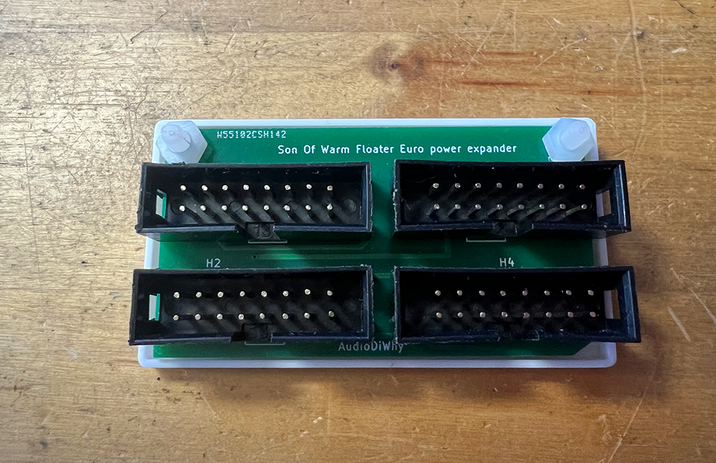
As my first FreeCAD project I created a tray for the Improved Warm Floater (initial post here)--the Warm Floater is a small PCB allowing 3 Euro modules to be powered by a single 16 conductor ribbon.  

The improved floater circuit board employs box headers in an effort to make it nearly impossible to orient the power cables incorrectly.  

I needed to create a tray for the PCB, insuring its contacts can't short against a conductive surface.

How did it go? So-so. Freecad is a complex program with a complex user interface; you won't be able to use it without a fair amount of study and practice.  

After a few evenings I got it working--fortunately there are almost endless youtube tutorial videos about FreeCad, although FreeCad's UI has changed over the years, so I had to refer to newer tutorials.

And I needed to remember: FreeCAD is free. No whining!

FREECAD WORKFLOW

I downloaded FreeCAD for Windows (here) and opened the program.
 
The first concept I had to understand was a FreeCAD "workbench". In FreeCAD parlance, your workbench is akin to a box of tools for building things.

For designing 3D parts like what's in today's post the workbench of choice was Part Design, chosen from a drop down in the main menu.

If I didn't choose the Part Design workbench, the steps below, their icons, their dialogs, and so on, didn't behave as expected or weren't visible at all.


In Part Design I create(d) a body then create(d) a sketch" (links were on the left side of the screen).  

I clicked on the XY-plane to anchor my sketch to it.  

Clicking OK, the workspace dropdown automatically changed to "Sketcher":


Sketcher is a 2D drawing tool, FreeCAD revolves around the idea of creating 2D drawing then turning them in 3D models. 

Using the 2D tools, I was ready to draw something in 2D; I created the outer rectangle of my tray.

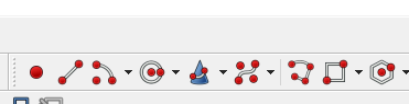
I found FreeCAD's icons to be confusing. For instance, here are 2D sketch tools. The rectangle and circle are obvious; The dunce cap? I still have no idea what the hell that one does.

Once I had my rectangle, I had to constrain it. I was unfamiliar with "constraining" my sketches, this meant, locking down the 2D proportions

A good video about how sketch constraints work is here.  A good design left no unconstrained dimensions; but at first I kept getting at least one "DOF" ("degree of freedom"--as in the online dating world, DOF is not always wanted) and found I was "under constrained" which in terms of coffee dates: about right.

Dof!!  
 

Constraining the shapes for my simple tray was easy enough however and after some practice constraining simple 2D shapes became pretty quick.  Update 7-12-25 for version 1.01 of Freecad you get at the basic constraint tools with an icon I hadn't seen before:


Clicking the down arrow you can see tools to constrain vertically, horizontally, set the radius or diameter of a circle and so on.

Once constraints were set, I clicked on CLOSE which closed the sketch and brought me back to the "part design" workbench.  A handy sketch tools dialog appeared, with choices like pad (which meant, extrude); hole (which allowed for tapered screwholes) and so on, but if I clicked anywhere else in FreeCAD this dialog went away and didn't readily come back....


....fortunately the same actions were found as icons along the top menu:


The next thing I did to my 2D shape was pad it (extrude it upward in the positive Z access).  OK, I padded to 3mm.

Next things got tricky. 

To create the tray I had to create a second sketch inside the first sketch, then"pocket" my design, "Pocket" is another FreeCAD term that was new to me.

This wasn't how I assumed you'd do this, why not have a command "make a lip" or whatever, but, nope. Every shape/cut/extrusion/screw hole in FreeCAD needed its own 2D sketch.  

I thought I could create this inner sketch by clicking the sketch icon in the main menu and creating another rectangle--but--nope. 

The 2nd sketch appeared to be hidden by the first. Drat!
I couldn't see this second sketch until I viewed the part from the bottom....that's where sketch 2 was created, BELOW the original one (not what I would have expected, nor what I wanted).  

What I need to do instead was choose the topmost plane of the initially created sketch by single clicking it.  

This "surface selection" (my term) only worked for creating additional sketches when the plane was the only thing colored:

Very important to make sure the surface I wanted my new sketch to sit on was colored, as you see here.  Otherwise the new 2D sketch didn't appear in a useful manner.

Now if I created a new sketch its Z origin sat on the green plane. Ah, that's what I wanted!

I created the inner sketch then constrained it to be exactly 1mm inside the first (is there another command "make the new sketch 1mm in every direction smaller than the one I just drew"? There must be....)

Finally clicked on a line of the inner sketch and clicked on the "pocket" icon. I chose a "dimension" pocket which was the default.

I entered 1mm and it worked.

Next, I needed 2 holes in the bottom of the tray.

When I tried adding the 2 holes to my first sketch I discovered once again--everything in FreeCAD with different Z extrusions had to be its own sketch and must sit on the correct plane.

I created a 3rd sketch, again choosing the surface I wanted the new sketches to sit on.  

This third sketch consisted of two constrained 3mm circles that would form the holes used to mount the PCB to the tray using nylon screws and nuts. 

Following the process above I "pocketed" the circles to push them though the inner tray (Sketch 2). 

I found no other way to do this, and this seemed like a whole lot of steps, that had to be done in exactly the right order, to make what I felt was an extremely simple 3D shape.  

But, it was done.

VIEWING THINGS IN FREECAD

To view or hide planes, you have to select the plane, right click, and say "toggle visibility". See the video here.

To zoom in or out use the mouse wheel.  Arrow keys move the imagine L/R or Up/Down.

To move around in 3D, hold the Shift key down along with the right mouse button. Click on an element in your part.  Now move the mouse. You knew this right? 

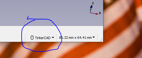
Probably not. Fortunately, I could change to different settings for rotating in 3D with my mouse (good video for setting up FreeCAD is here)--the "TinkerCad" choice is in the bottom right of the screen. Tinkercad allows 3D rotation using just the right mouse button. Better!


One more tidbit, you use "draft" workbench to create text. See the video here.

EXPORTING 3D MODELS TO KICAD

You need to install a 3rd party tool for this: KiCad StepUp.  Video on how to do this is here.  

The name of the tool is "Kicad StepUp. Once this tool is installed, I selected the body of my model and chose the KiCadStepUp workbench.  It threw an error "Requests not found" but I ignored that.

Then I clicked on the KSU export to Kicad button and used all the defaults. It told me where it saved my exported files (".wrl" and ".step" files) which I renamed and moved.  

The 3D image could now be imported into Kicad. I opened Kicad, and using Kicad's Footprint editor used the file > footprint properties > 3D model tab.
 

Update: FreeCAD allows exporting to WRL without a 3rd party tool. Select the entire 3D model; file > export. In Kicad: footprint editor; open a footprint; file > footprint properties > 3D tab.

TURNING THE DESIGN INTO TRAYS

With my tray finally done I printed one of these out on my 3D printer--which worked!--but needed more of them.  


So....With my tray STL file in hand, I whipped up a simple PCB uploaded both to PCBWAY, yes they do 3D printing, and wham, it was back. The 3D print jobs looked great. I am not saying this just because they're my sponsor, really, the quality of the print was top notch. 


Let's build!


3mm nylon screws and nuts fastens the PCB to the tray


This got mounted in my bench rack, now I can put more modules with low current draw in there....much needed improvement.

I figure I will get better at Freecad over time....this still feels very new to me. 

See ya next time.