RP2040--Simple C Library for SSD1306 displays

For upcoming projects I want to include SSD1306 based displays for RP2040 based audio projects. Easy in Micropython, but what should we use for Embedded C?  

No-name, super cheap I2C SSD1306 OLED display.
Gotta love the umlaut in "menu"!

I found a really good C library for this application. written by David Schramm, here. It gives us useful 1306 display functions without extra bloat.

This time: I get this library working on the bench: different strings showing up on the OLED based on the position of a rotary encoder.

I also get additional font.h files working with the library, from content found here.

Working on the bench....

Use your Library Card!


This is the same idea as the Atmel 328 SSD1306 C library described in this post, but with a different MCU. 

I could have written my own library for the 1306 OLED but didn't have time, so I used this library's abstrations instead. 

Documentation for this SSD1306 I2C C RP2040 library are here.

The development board chosen for testing was the Raspberry Pi Pico. 

Writing the code

First up was to get the example code working which was really easy. 

I downloaded the library and code examples here and loaded it into my usual toolset: Pico/Pico SDK and VSCODE, running on an Ubutu VM--posts for my RP2040 C toolchain begin here.

The library's provided test code compiled first time with no issues--impressive! I had this all up and running in about 15 minutes.  The example code showed some basic graphics and a few different fonts whizzing by on the OLED. 

So far, so good!

On to see if I could get a rotary encoder to display "CW" and "CCW" as the encoder was rotated, well, clockwise and counter-clockwise ("anti-clockwise" in the UK, which is a much better phrase).

I had trouble with this, and it was my own fault.  

Here we go....

Encoders and Hardware


I bought a bag of surplus top-shelf ALPS encoders that had incorrect documentation. These were high quality encoders at a ridiculously inexpensive alibaba price--but as I say so often--what is my time worth really? 

Turns out its pins were wired up the same as every other 3 pin encoder I have ever seen.  The included photocopied documentation was just plain wrong. 

Doh!
High quality, surplus encoders. Usually cost $3.25USD or so each, I paid something like .25c USD each. How could I fail?


Sketchy Xeroxed documentation that came with the surplus ALPS parts (no designation of which ALPS encoder was on the part) had the ground on the leftmost pin--nope. Above is the correct wiring and conforms to most encoders out there. ARRRG!!! No, I can't show you a scan of the incorrect documentation, because I lit a match and burned it.


Wiring used to test the OLED from a rotary encoder. For power: connect 3.3V bench power to pin 39/VSYS ("-2" on some RP2040 pin diagrams); bench GND to RP2040 38/"-3"; 1306 Vcc pin to regulated 3.3V power on RP2040 (36/"-5"). PICO Pin1 is TX; hook it to RX on your serial reader.


Breadboard test setup

Next it's on to this post's stupid coding mistakes. 

It had to do with how I was reading the encoder. 

But first, I need a few minutes to talk about how the encoder was being read by my test code....

A line of code in main.c's infinite loop sensed if the encoder state had changed at all; then, saw if A and B were the same or different. If they were the same, the encoder was turning one way, if different, the other. Read more here, this is a pretty standard "read the encoder" algorithm. Easy, right? 

Not for me. I used the UART based reboot code found in a previous post (here), but the UART reboot code has a scanf()which made the loop break. Until this was commented out, the encoder didn't work at all.  

Time wasted: twenty minutes?

However it was the next dumb mistake that cost me an entire weekend day.  

I put a sleep_ms(200) into the main loop. The idea was to...well I am not sure really why I put that in there!  This made the encoder's outputs almost always read "both 1s or "both 0's"....so, the sleep statement broke things. After sleeping the main.c woke up and queried the rotaty encoder to see if the encoder state had changed but it was--too late!! I had to catch the encoder's lows and highs right when they change...which means the main.c loop had to always run unimpeded. 

Took me a while to find the errant single line of code and get rid of it.

I will go into more detail about encoders and RP2040 in a future post. The encoder read really should to be done with interrupts, not a loop. But not now--fixed--onward.

OK, with the encoder sorted, it was time to move on to the OLED itself.  

CHANGING AND MANAGING FONTS


There is a string function in the library that allows you to argue in the font you want to use--cool!  

ssd1306_draw_string_with_font(&disp, 8, 24, 2, fonts[2], str1);

And the sample library provides 4 fonts, but 3 of them weren't that useful to me, more designed to show off some of the odd characters you can display on a 1306 vs. things I would use in a project.

Good news, you can get more fonts for the library, using content found here

Even better, the fonts repo has PNG files that show how the fonts will look on the OLED once compiled. Very cool!

You have to edit the .h files a bit to make them work with the library--not too hard--here are my bench notes describing how to edit them:


/* how to use font.h included here 
See  https://jared.geek.nz/2014/jan/custom-fonts-for-microcontrollers#drawing-fonts

--#include the font in main.c

#include "fivexfive_font.h" //name of edited font file

--call the font in main.c (add it to fonts array 

so add the font file (without the .h!) at the end of this array in main.c
const uint8_t *fonts[6]= {acme_font, bubblesstandard_font, crackers_font, BMSPA_font, renew_font,fivebyfive_font};)

then call it: fonts[5]   eg:

ssd1306_draw_string_with_font(&disp, 8, 24, 2, fonts[5], str1);

You also have to modify the .h font files to work at all, or else the imported font files won't compile.

In general, Use existing [font.h] files included with the 1306 library as an example of how to format the new .h files:

in the font.h file get rid this line:

const unsigned char font[96][6] 

and use this instead

const unsigned char fivebyfive[ ] = {

where fivebyfive is the name of the font file without the .h extension, elmo!

for the first row use this

8, 7, 0, 32, 126,

where 7 is the number of columns in the array (usually 6 or 7) and the 0 is extra # of spaces you want between letters.

Get rid of the extra curlies in the guts of the array data,i.e., all the rows with 0x00, 0x70, 0x00,0x00, 0x70, 0x00 but leave a single curly at the beginning and a curly and ; end of each font
.h "how will the letter look?" data. 

save everything and compile

Test it.


*/

Ha!  I edited 2 of the font.h files for the library.  They are included in the github repo that captures the test code for this post. And they work....

DEBOUNCING THE ENCODER

It became obvious quickly that some better debouncing of the encoder was needed. The CW and CCW track some of the time, but not all the time..

I found an interesting "software filter" idea (for Arduino--but should work for any MCU) here.  

My adaptation of this:

static uint16_t stateA=0,counter=0;

 stateA=(stateA<<1) | gpio_get(ENC_A) | 0xe000;
 if (stateA==0xf000)
{

//trap encoder stuff here.
}

StateA  fills up LSB to MSB; then we see if the LSB values are jumping around.  

If so, don't do anything. Once it's stablized, proceed.

I have had mixed results with this code addition. An RC filter is still needed to get rid of chatter and only slower turns of the encoder are seen. I continue to bounce around.
 

OUTTRO


In case you missed it--you can get the code I used in this post from github, here.

And/Or--get a simulation in Wiwok: here.   

Victory!

With this set, the "CW" and "CCW" strings look good in various fonts. I still had some encoder issues however as I describe above. Most of the time the correct string is shown on the OLED, I figure when it displays incorrect data it is because better debouncing for the encoder is needed.  

Again I will dig into encoders and encoder debouncing in greater detail in a future post. 

Until then, code well and live!


RP2040 DMA, a Plug, and a Great YouTube Find

Hello again!

This time I continue to plug away at the RP2040, the processor I started messing around with during "shelter in place."

This time we will look into running DMA embedded C code on this superb microprocessor.  
All hail the RPi RP2040!


 BUT FIRST--A MESSAGE ABOUT MY SPONSOR

I don't do this sort of plug often, really almost never, but the good folks at PCBWAY have been going the extra mile for this blog for a long time now and deserve a bit of extra love.

They approached me a few years ago with a sponsorship deal--something I didn't think much about before I got their "is this real?" email. 

The offer surprised me--this blog was my trail of crumbs to help me remember whatever new self-taught EE skills I stumbled upon....the blog can be extremely geeky and well off the beaten path at times....some of my posts have a ton of views but some not so many...I never considered any sort of sponsorship or monetization.  

But, I said: sure. 

I had used PCBWAY's services before the deal began and had really good interactions with them....PCBWAY offered services at a low price, things I couldn't find elsewhere--for instance,  affordable sheet aluminum fabrication I used for front panels—yes, in a previous life I used aluminum sheet and a thermal decal process for electronics projects:

With a huge amount of PCBWAY's support my front panels are looking better I think--PCBWAY manufacturers the PCBs I use for this blog, provides the 3D printing for brackets and whatnot, as well fabricating as the front panels I use in my rack.   


Anything I've ever gotten from PCBWAY has been super solid, of great quality, and they have always gotten the boards to me very quickly. 


Most of all I've been impressed with how friendly their staff is. Super nice, very enthusiastic, very helpful. Funny, they're half a world away, but they feel a lot closer than that.


So yes this is a blatant plug, think banana jacks, but really, for all the help they've given me over the past few years, a washed up rock and roller with a virtual machine and a soldering iron, the good folks at PCBWAY deserve a big shout out. 

They let me post any sort of tech I want, are always upbeat, and encourage me to keep trying new things. So: if you need fab or whatever, please, give them a shot. Tell 'em audiodiwhy sent ya.  

OK on with the post.

DMA

I've done zero work with DMA to date.   

The elevator pitch: data is sent to or from memory to a peripheral without bogging down the processor--in fact, DMA involves little to no processor interaction at all. 

Good general introductions to DMA are here and here--a million and one uses, especially since when processing digital audio we have to move data around fast

So, where to start?  

The DMA function calls from the Pico SDK and RPi's embedded C examples were a bit daunting. I needed to look elsewhere.

To this end I googled the stuffing out of "RPi Pico DMA" and its variations.  

This led me to a wonderful series of videos by Cornell lecturer Hunter Adams. He took the content of one of the EE/CS courses he teaches--ECE 4760/5730--and put it on YouTube.

ECE 4760 covers DMA in depth but a whole lot more. Think of it like this: everything you ever wanted to know about RP2040s....as well as other far ranging topics....extremely useful for all kinds of things we do...rolled into a single semester blow-out.

This guy is a terrific, top-notch explainer, he's enthusiastic and encourages his students to get involved and passionate about projects, he's entertaining, and his example code is useful and exceptionally well documented. 

Begs the question--back in my day, why the hell didn't Cal have anyone on staff who took teaching undergraduate EE seriously? 

Run, don't walk, and check out his videos, starting here.  

Makes me wish I was young again.....

OK....after emailing Mr Adams to get permission to use the his code (he said OK) I got my first DMA bench experiment working, get the embedded C here.  

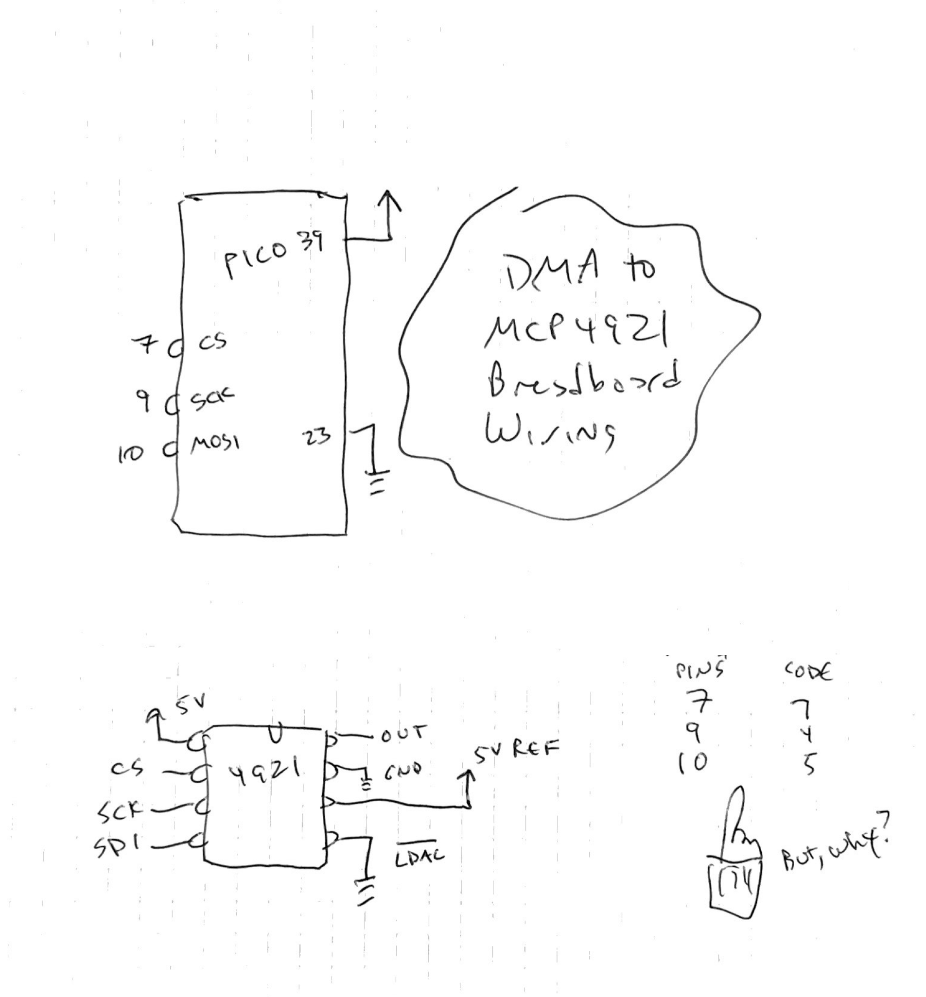
Here is the wiring I used:

Victory! Sine wave at output, derived from DMA--with no code in processor main() loop. 

Very Nice.

I went through the code, trying to understand what each part of it did. Fortunately Hunter's documentation is extremely thorough so this wasn't too onerous. 

Again, you can get his code and documentation here.  Unasked for advice: Don't just compile the code and upload it--to paraphrase Michael jackson--just Read It! I won't repeat what Mr. Hunter's notes here, rather, present some of the takeaways of my own.


FORMING 16 BIT WORDS 

When using DMA to send data to a SPI peripheral, each 16 bit word has to have control and data good to go. 

This makes sense, since we don't have a microprocessor at our disposal to change out 4 MSB's for each SPI write, or anything else, really. What you put into memory is what the peripheral is going to get.

The code assumes the DAC uses 4 MSBs for control and 12 LSB for data. I used an MCP4921 which luckily conforms.

The control word I used:

#define DAC_config_chan_A 0b0011000000000000

GPIO PINS

When I first fired up the bench experiment I got--nothing. 

I stuck an oscilloscope on the MCP4921, as I suspected SPI wasn't working--it wasn't. The serial input and clock pins showed no signal. That's not SPI, that's ground!

Turns out SCK and MOSI signals were appearing on the wrong (?) pins....

I ended up using this code modification which worked:

#define PIN_MISO 6  /// not used
#define PIN_CS   7   // Pico pin 7
#define PIN_SCK  4   // pico pin 9
#define PIN_MOSI 5   // pico pin 10
 
But I still can't figure out why SPI data showed up on pins 9 and 10--the pin #'s from schematics (RP2040--see page 10; Pico--page 24) didn't tell me why pins 9 and 10 were involved at all. But from looking at things with a 'scope--and hearing a sine wave coming out of the MCP4921's output--they clearly were the correct pins based on the code.

I must have missed something simple!  In future projects I figure this will come up again and I will need to figure this out. 

But for now I will take the fact that the circuit works as a win.

SPI

(You have to understand basics of SPI for this to make sense--a good introduction to the SPI protocol is here).

Another thing I have not seen before is this call from the Pico SDK:

gpio_set_function();

The argument for this function is taken from an enum; for SPI, its value is 1. This appears to make the RP2040 smart about using a particular GPIO pin for Chip Select. I didn't know about this.

Here is what I think is going on:

In SPI code I've written to date I've set Chip Select ("CS") to 1 and 0 as needed, but this function seems to tell RP2040 to do this heavy lifting for us. Exactly why/how it works this way is unclear--does this 1 value set a register somewhere and make CS work with less code?  It must.

Update 9-21-24: The .h file for gpio_set_ function() is here

This SDK call means you can program a GPIO pin to function as needed with a single line of code. CS (1) is one of them, but there are more. The same functionality is possible using C without the SDK or setting the registers coding in assembly, but using the C/C++ SDK the programming is easier. That's why we use the SDK.


All of it--interesting! Lots to learn here.  

OUTTRO

Up next--I bought some inexpensive CODEC ICs, it would be interesting if I could port this code to move data from memory to a Codec. 

I hope to have that working and written up in a future post.

The DMA functions are still very new to me, but I am happy to get this on the bench and working. 

Onward!

Small MS20 Filter PCB--Eurorack Ready

I am porting some old Frac Format synthesizer modules I built over the past few years....I am out of space in my studio so I want to port them to a slightly smaller Eurorack "skiff" format.  

Euro is still a bit new to me....but is the way of the present and future.  

Some design goals for these ports:

  • Small footprint throughout
  • Some SMD components but let's use through-hole where we can, so it's easy to build.
  • Modular--so you can mix and match PCBs with future projects
  • Want a stereo version?  Make two. Want a Quad version? Make four.  
  • 100 mil edge connectors and minimal hookup wire
First up is a classic Korg MS20 filter clone based on the classic Rene Schmitz-bits layout. You can find Rene's interpretation about a million places on the Internet--LookMa has cloned this filter, LanterTronics has cloned this filter. I previously cloned this filter

Behringer may have cloned the "rene" interpretation of this filter for their K2?--don't know, but, knowing those guys--probably.

MS20 filter clone on the bench--Seems working!

Let's cut the blah blah ginger blah blah and get right to some useless build photos:

A happily bagged boardlette from this blog's sponsor--PCBWAY.  Please help out this blog and check 'em out for your next DIY project.


Op amps are SOIC SMD.  I can solder these without a microscope or magnifying glass....

Board layout.....  

Easy build....Ready to test!

Wiring used to test the design. The dots down the center are male 100mil PCB edge connectors.  

As an homage to Rene I used CA3080 OTA ICs; slightly hard to find but still out there, as of writing this post Jameco and Small Bear have them in stock....the design can be pretty easily ported to 13700 OTAs, an IC that is currently a bit easier to find; if there is interest comment below....but if you have skills with Eagle it would be pretty to grab eagle files off the PCBWAY community site and swap a 13700 into the sch and brd file yourself.

On the bench this small VCF board pretty much tested working first time....I didn't read my own notes on the previous Frac build (doh!) so I repeated a few of the same mistakes, but they were easily fixed. 

I have posted the gerber, PDFs, BOM, eagle files etc. on the PCB on PCBWAY's community page (here)....I hope to wrap this Euro port up in the next few weeks--I am currently finishing up a layout for a stereo pots n jacks board and a Euro formatted 14HP front panel. I will upload all those soon.  

Until then--don't breathe the fumes!

AD9833 Volt/Octave VCO--New Jacks n' Pots Board--I am happy!

 Last post on this VCO, for a while anyway?  Hope!

AD9833/RP2040 VCO--seems WORKING

I took a month off and it helped! 

This module was driving me nuts. 

I got a fresh start March 1st and got the damn thing working after a single morning.  

There are too many previous posts about everything that went into designing, programming, laying out, and building the AD9833/RP2040 VCO, for instance:

  • C library for AD9833 Function generator IC for the RP2040 MCUhere.
  • AD9833 Triangle out to Ramp/Pulse board: here.
  • SEEED buffer board for SEEED XAIO 2040 RP2040 MCU dev board: here.
  • SPI library for RP2040: here
  • UART for debugging: here
  • Toolchain for RP2040/Ubuntu Linux/VMware virtual machine starts here.
  • Getting volt-octave working on the bench: here.
  • Getting the initial chock-full-o'-errors Euro skiff  build working: here.

BUILDING THE VCO

I knew I had to replace the pots n' jacks board from the previous revision--this is the board that sits behind the front panel--as it had some stoopid mistakes. 

I redesigned the board and sent it off for fabrication to this blog's ever-patient sponsor, PCBWAY....


Happiness is new PCBs from this blog's sponsor, PCBWAY.  Please help this blog and check them out--clicking on the link helps a lot--also take a look at their community pages, here.

I used a hot air tool to melt the pots' solder joints and get them off the previous board.  At $2USD or so per pot it was good to reuse them. 

Success--ready to reuse........

Next, I built the revised pots n' jacks board--resistors first:


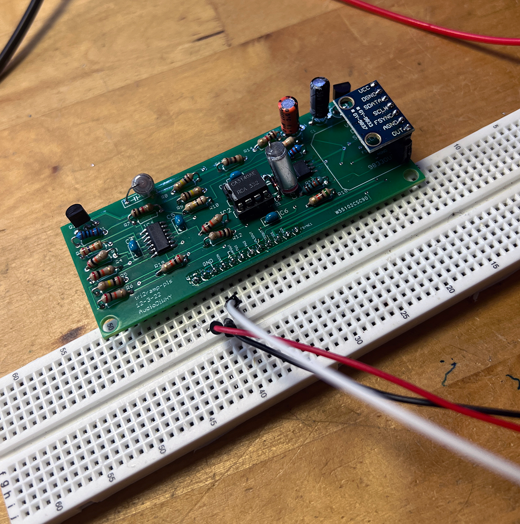
Then the RP2040/SEEED breakout/buffer board and tri-ramp-pulse PCBs were attached to back of the pots n jacks board:


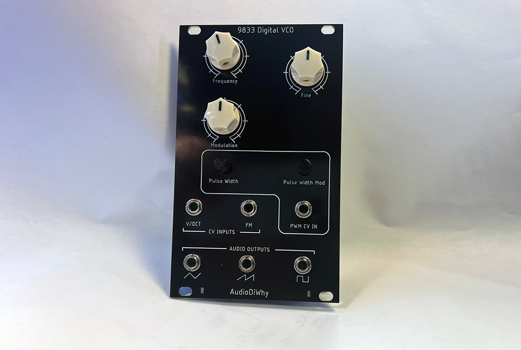
Front panel mounted--ready to test:


HOW IT CAME OUT....

To my surprise, after the new "motherboard" was deployed, the VCO sounded and worked--GREAT! 

The pitch jitter was gone--not sure what was causing it before--I thought I had to upgrade to a 14 bit ADC instead of 12 bits, but, no--12 bits seemed fine for this application.  

To test, I used the CV output of my MIDI to CV generator (intelligel uMIDI), multed it with a Mutable links and fed the volt per octave signal to the AD9833 VCO in parallel with a trusted analog VCO: a Doepfer A-111-3 Micro Precision VCO / LFO

These two were mixed through a CP3 clone mixer and presented directly to Ableton Live.

I wanted see how how they sounded together:

  • How well did the AD9833/RP2040 VCO track compared to the Doepfer-smoker 111 for volt/octave tracking?
  • Same question for portamento and pitch bend
  • How did its FM modulation input sound?
  • How "analog" did the AudioDiWHY AD9833 VCO sound in general?

The jury is in.

The AD9833 VCO behaved and sounded--trying to be objective here?--fantastic

No drift from this VCO, no overt temp/pitch issues, no oddness when tracking all over the place along side the Doepfer; to my ears both stayed in tune over at least 6 octaves, maybe 7. 

For what I do--definitely good enough.  

Pitch and glide sounded the same for either VCO.

FM modulation for the AD9833 VCO sounded as you'd expect. Pleasingly warbly, buzzy, to ring-moddy.

Best of all, this digital VCO sounded "analog" to my ears--between some distortion in the triangle to pulse/ramp conversion errors, and whatever slight errors are caused by the 12 bit A/D, I got a few slight pitch drift issues and a small bit of analog output oddness, the same sort of miniscule errors I get from the many analog VCO's I have in my rig.

The AD9833 VCO's pulse width controls were aggressive (?), but sonically pleasing.

The ramp audio output is a bit distorted but had a pleasing and very usable buzzy rampy sound.

In general, for all the consternation, fear and loathing with this build, in the end, I was happy...

I wanted a digital VCO that sounded analog, and think i got that, but more important, I wanted to see if I could bring together the many many hours spent learning embedded C, self-taught electrical engineering, pondering what makes something I like "sound good" and improving my PCB design skills--the "geeking" (as my psychiatrist girlfriend/fiance calls it) that went way up during the pandemic...and ultimately make something challenging that is useful in my Eurorack....  

HOW TO BUILD IT

If you want to play along at home:

You can get the embedded C files, CMAKE files, firmware (including ready-to-use .uf2 file--drag and drop it directly to the RP2040--so, no need to compile or have a working C toolchain) and all other code needed for this project from github, here.  

Then get hardware files--gerbers for the 4 PCBs, BOMs, Eagle CAD files, and a PDF of the board layout, from another github repo here

You can also purchase the PCBs through PCB way's community site, here, but I'd recommend getting all the gerbers from Github first--they will be most current.

Make sure to read the BOMs which have specific information and tips about components and hardware used.

Hopefully from there it should be like building a kit.

A note on components: to get volt/octave response I used these values on the SEEED dev board, then adjusted T1 to get volt/octave response.

  • 50K 25 turn trimmer for T1 (use a high quality trimmer for this)
  • 47K 1% for R8
  • 100K 1% for R5
  • 22K 1% for R6

OUTTRO

Improvements? Of course.  

How about a second FM input?  That would be easy to add but would take up front space--maybe too much.  For now I'll use a CV mixer. 

The triangle to ramp conversion could be improved to distort less: perhaps use a JFET instead of a 2N7000 mosfet, include additional comparators, other things--but I like the way the one I have now sounds. For now it stays.

A rotary switch to jump between octaves?  

I think at least for now, I'm done with this. Time to move on.

I know I complain about the WHY in AudioDIwhy.  But when something works well it's fun. 

That's the idea, right?

AD9833 Audio VCO--Works But not Finished


 I finally have the AD9833-VCO working! Eurorack format.

The fun starts with the AD9833 post here. I wrote a C library for it....then I did this thing with the AD9833, then this thing, then that thing, then something else--I have to link all those posts?

Too lazy, if you want to know the history of the function generator IC used in this VCO, please search this blog for "VCO". 

This blog is chock-a-block full of posts about the handy AD9833--I have written more about this function generator IC than I should have....to cut my teeth on embedded C, SPI, UARTs, and everything else we know and sing. 


WORKS, BUT NOT FINISHED!

This has been a laborious project--as always, still, more work needed....

The 12-bit Seeed ADC buffer board--good for a lot of projects--may not be the right solution here. Best I can tell, 12 bit data gets lost in the A-D noise floor (I think?) and thus the audio output of the VCO is a bit jittery. I want to fix that. I could use a 14 bit ADC and just toss out the 2 LSB's. That might help?

Also the triangle to ramp PCB's ramp output (previous post here) a bit too buzzy sounding. There are ideas on Muff Wiggler about ameliorating that puppy.

For now it works, the VCO doesn't smoke, looks OK, tracks V/octave fine, and damn, I need to get this Rube Goldberg thing off my bench for a bit!

THE SIGNAL FLOW:


I mostly designed and built this VCO to see if I could figure out how to design and build this VCO. Makes sense?  There are lots of designs out there for audio synthesizer VCOs that are a lot simpler. This isn't one of those.

How it works:

Input is a volt/octave CV, modulation CV, and a frequency and fine control.  

These are mixed, buffered and clamped by the buffer board that incorporates a SEEED XAIO RP2040 dev board (see the previous post here, the buffer PCB is a PCBWAY community project; PCBWAY sponsors this blog--thanks!--if you want to build one, you can get the gerber here).  

The RP2040 on the SEEED dev board is running embedded C (current code revision of the code is on Github, here).  

It uses a python frequency lookup table array creator--which I turned turned into a .h file for this project (github repo for the Python array frequency creator is here). 

I also used the AD9833 C library I wrote for AD9833 (github here) and debugged using UART (post here). SPI is used to drive an AD9833 (again, lots of posts about this IC, for the VCO I used this cheap breakout board).  

The AD9833 has a 600mV unipolar triangle output--so yet another PCB is used to convert the triangle to ramp and pulse/PWM and buffer the 3 signal outputs....post for this subcircuit is here, modwiggler forum thread about the concept and design of the converter begins here

Yes, this is a complex build!  To make it even harder, the build uses no hookup wire and is configured in Eurorack skiff format. That makes it difficult to modify and inconvenient to troubleshoot, but, well, who likes things to be easy.

Build Photos:

Board fab was from this blog's sponsor, PCBWAY--please help out this blog and check 'em out.


testing the triangle to ramp converter....it works....


OUTTRO


I blew up a SEEED dev board getting this going, one AD9833 BoB was defective, and one SEEED board was DOA. A lot of swearing and head scratching has gone into this project so far.  Doh!

This experience has been pure DiWHY--such as, why am I building such a complex VCO when a 3340 based analog equivalent will probably sound better and be a hell of a lot easier to lay out and build?

DiWHY masochists: show you can take the pain and get yer zips for BOMs, gerbers, PDFs for the schematics and boards, and Eagle CAD files for this VCO, at Github here

If anyone wants to join in with further madness, message me through the MW forum and you can play along. or just grab the files and start modifying.  

In the meantime I am going to take some time off DiWhy--my pychiatrist fiance (amazing she accepted my marriage proposal right?) tells me I need a break. The Good Dr. is always right.

work on other projects for a few weeks or more to regain my DiWHY sanity. 

Then go back to this project. 

For instance, I already have a 14 bit ADC board to replace the 12 bit version used for this project. To skiff-ize the PCB, it uses a lot of tiny tiny SMD parts...should be a real pain in the butt to fabricate. Blah blah ginger blah blah? update 3-5-23: turns out the 12 bit ADC was fine, or at least good enough, issue was with other elements of the design.

....this project tied a lot of previous learning into one module, and getting it to perform better (better sounding ramp, better ADC performance, other improvements) will be good learning as well. I will say it yet again: in the words of immortal Emil Faber: "Knowledge is good"
 
Update 3-5-23: newer version of this VCO is here--greatly improving the design I think.

Back to work.

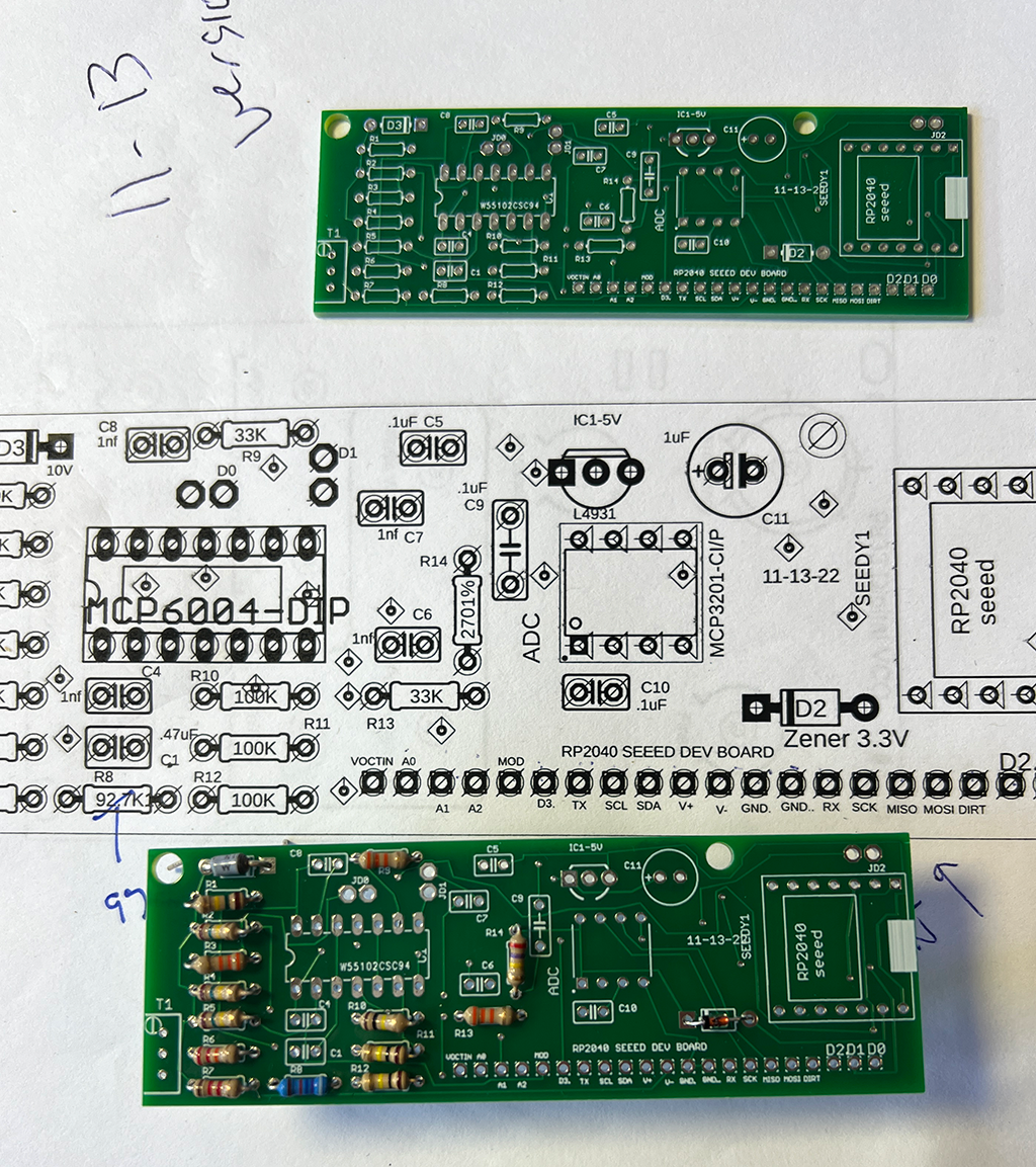
Improved SEEED RP2040 Buffer Board--Mutable Instruments Homage

Hi there, continuing to work on the AD9833 volt/VCO, it's raining endlessly here, I am in a crappy mood, and man I am getting tired of this damn VCO build. 

Ah yes. The RP2040-AD9833 audio VCO. Is it done yet? can we pretend it is?  Update 3-6-23: It's done and came out rel good! Thanks to these guys for support; more about the finished + working AD9833 based V/octave VCO here.


For the ADC and analog buffer portion of the VCO I lifted design basics from Mutable Instruments, who make fantastic open source synth modules:

  • MCP6004 low cost quad rail to rail op amp for analog input buffering and clamping
  • Unipolar operation for the op amp
  • Inverted input from buffer to the MCU (why not--saves parts--fix this in software--gotta love Mutable!). Everycircuit simulation of the idea is here.
  • Zeners for most of the voltage regulation--cheap and simple
  • a fifth 12-bit inexpensive ADC in addition to 4 provided by the RP2040 MCU (I'm not counting the on board ADC used to measure MCU temperature which isn't needed for the VCO)
  • other general improvement and fixes to my initial design stupidity 

I did a post for version 1 of this same idea (here) but it sucked, this version irons out a lot of kinks.

Get this buffer board--a dev board for a dev board?--from my sponsor's PCBWAY's project page, here.  You can also get gerbers for a lot of other AudioDIWHY projects from their community pages.

You will need the most excellent and very tiny SEEED XAIO RP2040 board to make it go.

 
Some improvements to the previous version of this buffer board:

  • Jumpers to enable digital or analog (JD0, JD1, JD2 on the schematic) for the the D0,1,2 MCU pins.  
  • Ground pour for bottom PCB copper (imagine that)
  • a 10K timmer and 96.7K resistor in series, along with a 33K resistor for the opamp's negative feedback, to get us very close to the necessary 3:1 ratio for incoming voltage to the dedicated ADC IC
Using the jumpers:
  • If you want to use a given op amp buffer stage, connect its two corresponding jumper pins.
  • If a jumper is disconnected: to prevent the unused op amp stage's output permanently slammed to its V+ rail, put a modest voltage (say 1/2V) at its non-inverting input.

Let's build it:

Happiness is a white box o' boards from this blog's trusty sponsor, PCBWAY:

Thanks as always to PCBWAY for sponsoring this blog....please help this blog and check them out.


Running the default blink sketch the whole thing worked first time and drew 40mA for the positive rail. The current draw from the older version was more like 150mA. Wow!! There must have been a stupid mistake I missed on the last iteration of this board, making it draw too much current.


Se habla blink? Claro que si.


We are ready to use this board for other projects!

More more MORE pcbs for the AD9933 VCO. Again: Are we done, yet?

Using the board should be straightforward.  If you are using ADC 0-1-2 (on the RP2040) you need to jumber JD0, 1, or 2 accordingly.  Otherwise, to use a digital in instead of buffered analog, leave JP0, 1 or 2 off. Also, if you are not using a given op amp stage you should leave C6/R10 (ADC0);  C7/R11 (ADC1); and/or C8/R12 (ADC2) off the PCB.  In this configuration, the unused buffer will get the -10V input signal which will keep the unused stage from flopping around at its output.

Onward....

Being a glutton for punishment I laid out pretty much the same board with a 14 bit ADC. Will it work more and better? We will see in the next few posts...but hopefully this damn VCO this board is going into will be done before the next global extinction event.  Update: With the VCO working the 12 bit MCP3201 ADC cuts the mustard. This was unexpected? So....for now the 14 bit version remains  unpopulated, but it will see life--assuming it works--in a future project.

Until then: Don't breathe the fumes--always bite off more than you can chew--stay in vegetables--eat your school.  

Happy New Year--Happy New ToolChain--APIO and TinyFPGA-BX

Hard to believe it's already 2023. Time flies when you’re having fun--and flies faster when you're being geeky.  

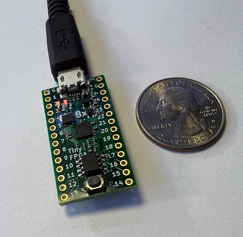
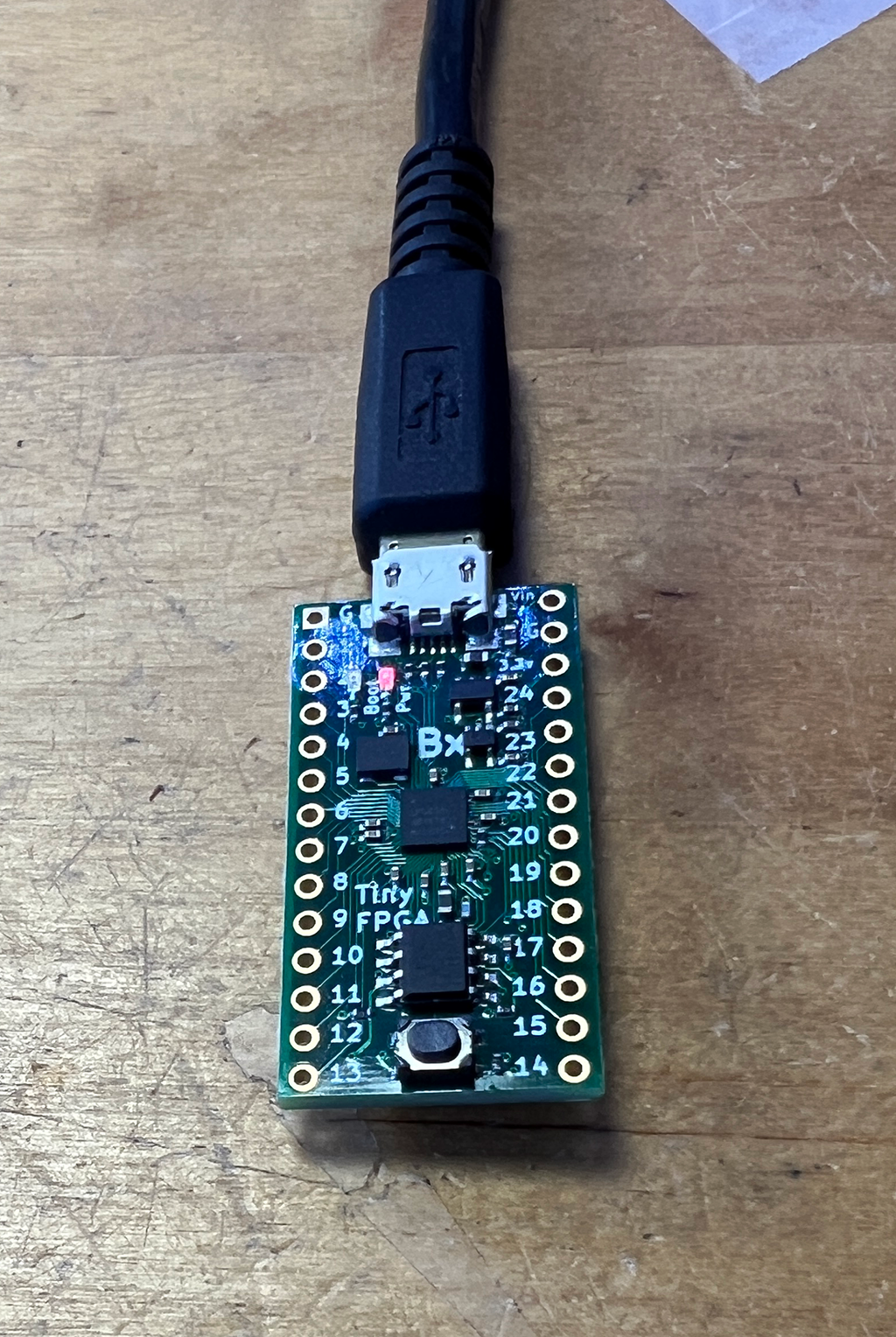
A year or so ago I bought a nifty dev board--the TinyFPGA-BX. It gets good reviews, is well documented and relatively affordable ($38USD).  

I figured this board would be a good starting point for learning, then using, FPGA's

FPGAs are the cool ICs where you can create your own logic "from scratch".  More here. But I know zilch about using these parts for AudioDiWhy. And I see a lot of cool FPGA use cases out there.

Almost zero knowledge is almost never good. Let's start trying to change that....

The TinyFPGA is indeed....tiny....

The New Year started with a long weekend--which means--time to plug in this FPGA development board and install a Toolchain.

Hours of Fun! 

But! The FPGA paradigm--hardware, software, all of it--was brand new for me--I needed guidance. 

YouTube. Of course.  

Shawn Hymel has an excellent (as always) video series about FPGA's, I started there.

Part I summarizes what FPGAs are and what they are commonly used for.

Part II goes over setting up the toolchain for Icestick....a development board very similar to the TinyFPGA-BX. 

Good news….Both Icestick and TinyFPGA-BX are supported by APIO, a popular open source development platform for similar FPGA's. So I set out getting that going....Getting APIO working was the crux of the biscuit:

GO APIO!


I decided to install APIO on Windows, not Ubuntu. I thought it would be easier to find help if I got stuck--Shawn Hymel, as well as many other users online it seemed, used Windows for this toolchain.

Apio relies on Python.....I have Python 3.11 on my Windows system--the latest Python build as of this post.  

I also installed Apio 0.6.7, not the latest Apio build. Shawn recommended using this older version.

For editing Apio project files I used Notepad++ which has syntax highlighting for Verilog--nice. Hint: if you use windows, run, don't walk, and get Notepad++.  A million and one uses!

The proof of concept for the toolchain setup was to get get a blink going on the TinyFPGA but at a frequency faster than what is found in APIO's examples.  Getting the basic blink should be easy--just load up APIO's example. But would it blink faster, Scotty?


TOOLCHAIN BASICS

I followed the setup steps in part II of Mr. Hymel's video--as well as steps found on the Apio website. 

I won't repeat all that here, please watch the video and read the webpage.

I had to make a few changes; not sure if it was because I was not using an Icestick, rather a tinyFPGA; using Python 3.11 and not an older version; using an old version of Apio; or something else.

I was using a different FPGA dev board so I used this to initialize my FPGA board:

apio init --board TinyFPGA-BX

When I tried to build an the example Blinky project, Apio would throw an error I didn't record--something about an issue with Python's click module

(Aside: Python click looks totally cool! I didn't know about this module! I am going to use it in future python projects....)

I guessed Python 3.11 was too new for the 0.6.7 version of Apio? Speculation....

Based on this hunch I upgraded to current Apio--cmd as local admin:

apio upgrade 

It still didn't build! 

It threw a different error; Apio told me to add tools-os-cad-suite. Perhaps this tool added functionailty needed for the TinyFPGA-BX. Not sure. Guessing still.

Again, I didn't record what I used to install this add-on, but the error message in Apio told me the exact syntax needed to install the tools-os-cad thingy. 

Fixed? 

Yes! Afterward I could "synthesize" a simple "Blinky" example:

apio build

Progress!  Synthesis seemed to work!

UPLOADING BUILDS 

Once the blinky code was synthesized--like C getting compiled I guessed? getting the dev board to eat code was next up.

Unlike the Icestick, the TinyFPGA-BX did not use an FTDI chip for USB to Serial. Instead it used tinyprog--some of the FPGA's gates do the USB to serial translation, not an external IC

This must have been a ton of work for a very skilled FPGA developer....You can see python code used to call it here. Very cool stuff.

But the damn thing still wouldn't eat .v files:

--tinyfpga not found

However running tinyprog -m  from elevated command prompt, yes, the dev board was recognized:

C:\Users\audiodiwhy\Dropbox\FPGA\apio-projects\tinyfpga-bx\BlinkyCL>tinyprog -m

[

  {

    "boardmeta": {

      "name": "TinyFPGA BX",

      "fpga": "ice40lp8k-cm81",

      "hver": "1.0.0",

      "uuid": "482fefbb-c6ce-4e08-aab8-84f55c23f788"

    },

    "bootmeta": {

      "bootloader": "TinyFPGA USB Bootloader",

      "bver": "1.0.1",

      "update": "https://tinyfpga.com/update/tinyfpga-bx",

      "addrmap": {

        "bootloader": "0x000a0-0x28000",

        "userimage": "0x28000-0x50000",

        "userdata": "0x50000-0x100000"

      }

    },

    "port": "COM3"

  }

]

Hello? 

I found a support page here--others with the same issue. 

The workaround:

  • run cmd as local administrator
  • cd to the directory of the project
  • run this instead from elevated cmd prompt: 
tinyprog -c COM3 --program hardware.bin   


COM3 had to match the com port found in the tinyprog -m output.

not sure why but--that worked!

MODIFYING THE .V FILE

In reboot mode the tinyFPGA had an LED-off fading to a LED-on, I wanted to create a more rapidly flashing LED to prove the toolchain worked.

Verilog isn't a programming language, rather a hardware description language.  Either way, I knew zilch about how to do anything useful. 

After making some random changes that made the LED go off (or change states so fast and slow it seemed like nothing was happening) I read a tiny sliver of how Verilog actually works. Imagine that! 

I eventually stole the fix from another web page, here.  

This .v file did the trick:

module Test (

  input CLK,    // 16MHz clock

    output LED,   // User/boot LED next to power LED

    output USBPU  // USB pull-up resistor

);

  // drive USB pull-up resistor to '0' to disable USB

  assign USBPU = 0;

  reg [19:0] counter = 0; // was [24:0]

  always @(posedge CLK) 

    counter <= counter + 1;

  assign LED = counter[19]; // was [19]

endmodule

From my limited understanding, [24:0] in the original Blinky sketch set up a 24 bit timer. I figured 19:0 would be faster since it's a 19 bit timer. It worked--the blinky blinked must faster.

UP AND OUT!

OK that's almost it for this time. 

I have a working toolchain for FPGA! 

I am still waiting for boards to come back from my loving sponsor, PCBWAY, (see, Wendy, I still got the plug in....)  But they aren't due back for another few days.....

So more coding, less fumes? If I have time, I will try to learn a few more things about Verilog.  

Onward! 

Until then, have a Happy Geeky New Year!