Hi there, continuing to work on the AD9833 volt/VCO, it's raining endlessly here, I am in a crappy mood, and man I am getting tired of this damn VCO build.
Ah yes. The RP2040-AD9833 audio VCO. Is it done yet? can we pretend it is? Update 3-6-23: It's done and came out rel good! Thanks to these guys for support; more about the finished + working AD9833 based V/octave VCO here.

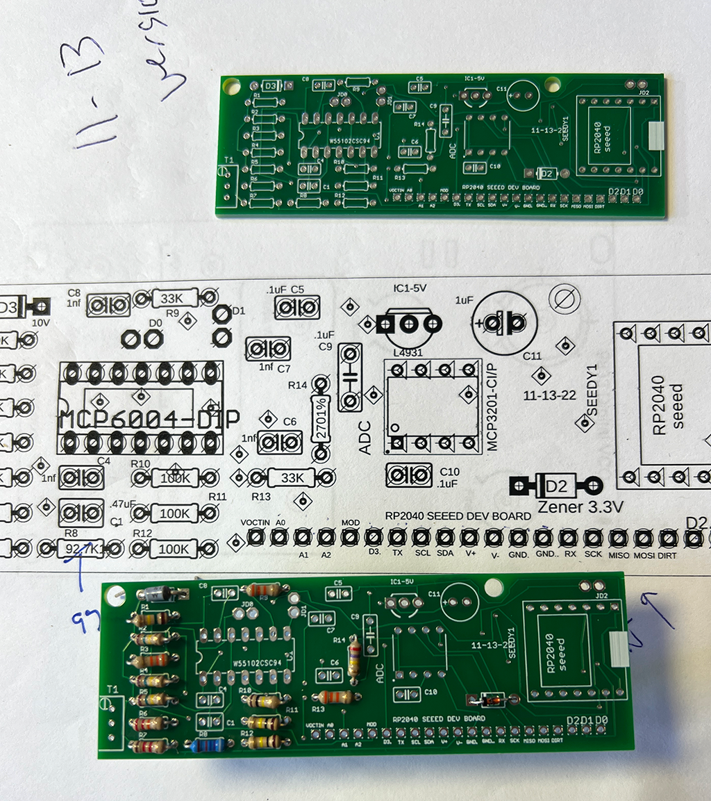
For the ADC and analog buffer portion of the VCO I lifted design basics from Mutable Instruments, who make fantastic open source synth modules:
- MCP6004 low cost quad rail to rail op amp for analog input buffering and clamping
- Unipolar operation for the op amp
- Inverted input from buffer to the MCU (why not--saves parts--fix this in software--gotta love Mutable!). Everycircuit simulation of the idea is here.
- Zeners for most of the voltage regulation--cheap and simple
- a fifth 12-bit inexpensive ADC in addition to 4 provided by the RP2040 MCU (I'm not counting the on board ADC used to measure MCU temperature which isn't needed for the VCO)
- other general improvement and fixes to my initial design stupidity
I did a post for version 1 of this same idea (here) but it sucked, this version irons out a lot of kinks.
Get this buffer board--a dev board for a dev board?--from my sponsor's PCBWAY's project page, here. You can also get gerbers for a lot of other AudioDIWHY projects from their community pages.
You will need the most excellent and very tiny SEEED XAIO RP2040 board to make it go.
- Jumpers to enable digital or analog (JD0, JD1, JD2 on the schematic) for the the D0,1,2 MCU pins.
- Ground pour for bottom PCB copper (imagine that)
- a 10K timmer and 96.7K resistor in series, along with a 33K resistor for the opamp's negative feedback, to get us very close to the necessary 3:1 ratio for incoming voltage to the dedicated ADC IC
- If you want to use a given op amp buffer stage, connect its two corresponding jumper pins.
- If a jumper is disconnected: to prevent the unused op amp stage's output permanently slammed to its V+ rail, put a modest voltage (say 1/2V) at its non-inverting input.
Happiness is a white box o' boards from this blog's trusty sponsor, PCBWAY:
 |
Thanks as always to PCBWAY for sponsoring this blog....please help this blog and check them out. |


 |
| More more MORE pcbs for the AD9933 VCO. Again: Are we done, yet? |


No comments:
Post a Comment