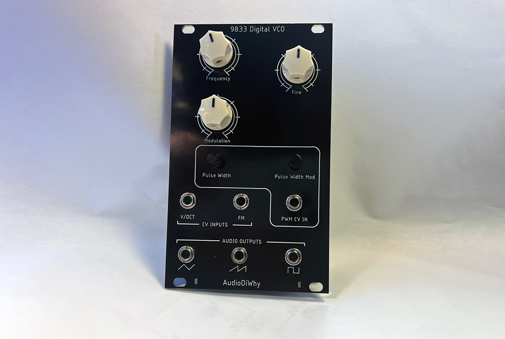
I finally have the AD9833-VCO working! Eurorack format.

WORKS, BUT NOT FINISHED!
This has been a laborious project--as always, still, more work needed....
The 12-bit Seeed ADC buffer board--good for a lot of projects--may not be the right solution here. Best I can tell, 12 bit data gets lost in the A-D noise floor (I think?) and thus the audio output of the VCO is a bit jittery. I want to fix that. I could use a 14 bit ADC and just toss out the 2 LSB's. That might help?
Also the triangle to ramp PCB's ramp output (previous post here) a bit too buzzy sounding. There are ideas on Muff Wiggler about ameliorating that puppy.
For now it works, the VCO doesn't smoke, looks OK, tracks V/octave fine, and damn, I need to get this Rube Goldberg thing off my bench for a bit!
THE SIGNAL FLOW:

I mostly designed and built this VCO to see if I could figure out how to design and build this VCO. Makes sense? There are lots of designs out there for audio synthesizer VCOs that are a lot simpler. This isn't one of those.
How it works:
Input is a volt/octave CV, modulation CV, and a frequency and fine control.
These are mixed, buffered and clamped by the buffer board that incorporates a SEEED XAIO RP2040 dev board (see the previous post here, the buffer PCB is a PCBWAY community project; PCBWAY sponsors this blog--thanks!--if you want to build one, you can get the gerber here).
The RP2040 on the SEEED dev board is running embedded C (current code revision of the code is on Github, here).
It uses a python frequency lookup table array creator--which I turned turned into a .h file for this project (github repo for the Python array frequency creator is here).
I also used the AD9833 C library I wrote for AD9833 (github here) and debugged using UART (post here). SPI is used to drive an AD9833 (again, lots of posts about this IC, for the VCO I used this cheap breakout board).
The AD9833 has a 600mV unipolar triangle output--so yet another PCB is used to convert the triangle to ramp and pulse/PWM and buffer the 3 signal outputs....post for this subcircuit is here, modwiggler forum thread about the concept and design of the converter begins here.
Yes, this is a complex build! To make it even harder, the build uses no hookup wire and is configured in Eurorack skiff format. That makes it difficult to modify and inconvenient to troubleshoot, but, well, who likes things to be easy.
Build Photos:
 |
| Board fab was from this blog's sponsor, PCBWAY--please help out this blog and check 'em out. |

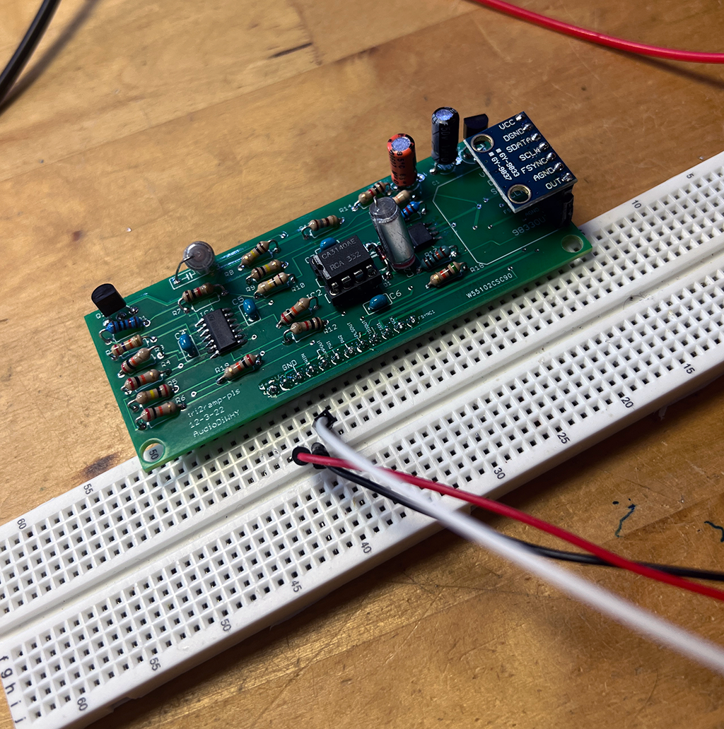 |
| testing the triangle to ramp converter....it works.... |
 |
| |


No comments:
Post a Comment