Good work Elmo--nice craftsmanship--impressive job on this.
The OCD in me hates electrical smoke but I guess it gets us all at some point.
Here's the VCO PCB that blew up real good:
 |
| I-IV-V: "wuz a TL074SMD.....now charcoal...." |
 |
| The front panel wasn't much better.... |
The other two CEM VCOs I built (post here) fared better--I used a "rev 2" PCB, correcting the mistakes of rev 1. That means: no kludges--and no smoke (yet) from either of these two (yet).

Lucky I was in the studio when the first VCO smoked right? Otherwise this could have really gotten bad.
So the question is, what happened?
Well being not 100% sure....I dug in a bit.
The TL074 IC used as a quad buffer in the VCO has built in short circuit protection, here is the schemo of a TL071 shamelessly lifted from TIs datasheet:

This means that any current going in or out of a TL07x hits a few resistors first. I didn't know these resistors were there at all, but even so.....as I see it, with +15/-15V power, you're going to be sinking a max of something like 75mA of current through this tiny resistor if you create a dead short to Edison ground. That's over one watt. Since this is an itty-bitty-IC-in-chip resistor, not the honking LotsaWatt resistors you'd find in a tube amp, the resistor can't be take that much punishment in terms of dissipating heat before saying good night.
There are also resistors between the + and - rails I can see in the TL071 schematic as well. Same sort of thing--you get a smidge of protection from overdoing the current from + to - from the looks of things, but there has to be limits to how much current you can put through any of these resistors before blowing up the FETS, transistors, or something else.
I like experimenting with innocent components....so I put a sacrificial TL071 on my bench, created a dead short from its output to ground (through an ammeter) than started cranking up the current from my bench supply. WARNING: do not try this at home!!! The op amp will heat up very fast, you could burn your house down. PLEASE ALWAYS BE CAREFUL!
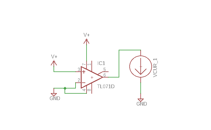
Here is my test circuit if you can even call it a circuit? The downward arrow represents my Fluke DVM set to read and display current:
 |
| The op amp became hot very quickly when wired up like this.....and could easily have smoked if I left it a few more minutes, possibly taking other things with it, like my entire lab. Again PLEASE DO NOT TRY THIS AT HOME! |
 |
| AudioDiWhy's lab dungeon of Op Amp Pain. |
The data sheet says a max for the FK package (not sure what FK means, perhaps FK-U since this is TI? Help me out here?) is 260C for one minute. I didn't record exactly how hot the TL071 got in my experiments but within a few seconds it was too hot to touch. Probably way less than 260C.
So what happened inside the IC during the torture test? Not sure exactly. There might be clamping circuitry I don't see in the schematic....or maybe I am missing something, but when first powering up my torture test the ammeter read around 20mA, I figure because I wasn't reading true Edison ground, so about what I'd expect as the max source output current from the IC, for a few seconds. But then the Fluke read 0A and the chip started to heat up fast. Even at 5V V+ and GND, in the config you see above, once the IC clamped, things heated up, to the point where I couldn't touch the IC, after maybe 15-20 seconds. Not good.
So I think it's safe to assume that in spite of the short protection the TL07x IC will get really hot if you present the output with a dead short to ground. The heat has to go somewhere.....
I didn't bother testing things like reverse voltage present at V+ vs. V-, since I know that will kill the IC straight away (been there, done that). So: don't do that either.
So I figure, what could have killed the vco was simple: one of the outputs of the VCO's TL074 buffer must have gotten shorted to ground by a wire or kludge or solder bit or something. From the burn marks it might have been a short on pin 8 pulling way too much current through V-.
 |
| All Hail Richie Blackmore! |
So what is my takeaway from all of this?
First--for modular applications, always use series output resistors for your output buffer op amps--at least 1K, on a TL0xx even though there is already a resistor inside. It isn't going to hurt to increase your short circuit protection.
Second--don't over kludge! This module was a horror show of daughter boards, hot glue, and 22 gauge bungies. Something was bound to go wrong, even though at first it "worked". Resist the urge--toss the overly kludged module and start over.
Third--Turn that sh*t off! YEP! always shut off all your DIY stuff when you are out of the studio, it's not UL listed and can blow up any time.

"Home, Charles": I took the smoked VCO out of the rack; time to rebuild it eh? I had left over extra rev 2 CEM VCO PCBs for this project--it was a pretty easy single evening job of using my rework tool to remove any parts I wanted to save from the blown out board and building up another main PCB, mounting it to remaining VCO guts, and calibrating it. Worked pretty much first time.
I also made the existing front panel a bit more presentable using "Mr Label", a vinyl sticker front panel process you can read about here.
Overall, good to have the 3rd VCO back, but I hope there isn't some sort of flaw in my VCO layout. I guess we will see; if I indeed screwwed it up I will be breathing many more fumes at some later date.
Such is life sheltered in place.


Maybe the original op-amp burned BECAUSE you were having people over... you know: "Demo Mode"...
ReplyDelete