Readers: If you'd like to build the project featured in today's post, please go to PCBWAY's Community pages--gerber file (main board); gerber for jacks board, front panel gerber, KiCAD project/pcb/schematic/library files, a B.O.M., some wiring diagrams, and more, can be found here.
The project also uses a small jacks PCB for the 3.5mm jack breakout, that project is here.
You can also help out this site immensely by checking out PCBWAY using the link here. Thanks!
=====
Hidee Ho boys and girls!
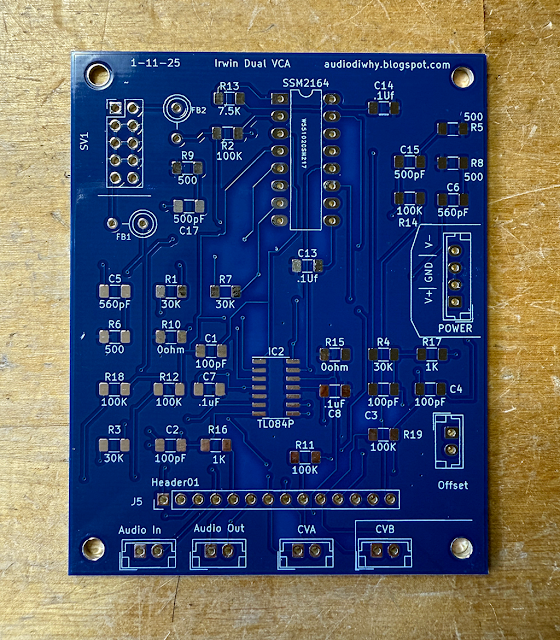
Last time I laid out an Irwin Dual VCA, this time I wanted to put it to work.
I designed and built a stereo panner in Frac Format....
.....to replace a similar build from 2004 (?) which of course I didn't document.
 |
| Right one looks better? |
The old panner was broken--the bias offset adjustment switches no longer worked making the audio agt output cut in and out in some applications.
Could I fix this 20+ year old module?
Not easily--when I inspected the old design I found that the add-on board for bias adjustment was wire wrapped--I did this?
DESIGN
I didn't document any of my work back in 2003 but could recall how the panner was conjured.
A quick sketch of the layout:
How it works:
Audio A+B is a mono input fed to normals: Audio A and B. Note--the Irwin VCA design can amplify and attenuate control voltags as well as audio, so the "audio source" can be any signal from DC to >18Khz.
Same idea for the modulation signal--single mono feeds 2 normals; plugging a 3.5mm jack into "A" or "B" overrides the normal.
Each modulation signal goes through a portamento subcircuit and 2 buffers; each buffer has an optional offset voltage (1/2 of a dual contentric potentiometer on the new build; a 5V SPST switch on the 2003 design). One CV buffer is inverted; each buffer output feeds one side of a center tap pot (datasheet here).
I considered adding a mixer for a combined A and B out, as well as 180 degree inversion of one or both audio inputs, but that would have overcomplicated the circuit; I already have lots of mixers and audio inverters in my rack, so I figured I would just patch them as needed.
CONSTRUCTION
....and in general the old module was built with (as my tech boss in the film business used to say) duct tape and snot.
I figured it would be easier to get new boards from this blog's faithful and ever-patient sponsor, PCBWAY, instead of reverse engineering then repairing my 20+ year old build--they always provide fantastic parts, and can assist in all your DIY needs, from 3D printing to assembly to metalwork and beyond.
You can greatly help this blog by checking them out: use the link here.
Back fast!
In the shipment I got a "jacks and pots" board.....

.... and a small PCB for 2x dual concentric pots--a personal favorite component for saving front panel space....
....as well as a front panel:
I figured I would use 4x40 standoff hardware to make modifications and fixes easier at this early stage of prototyping:
SMD AND JST
During the pandemic I found using 1206 SMD components was easiest for super-fast prototyping.
I often found myself wanting to change out parts and through-hole swaps were time consuming and occasionally destroyed pads on the PCB.
A previous post about my journey into SMD DIY is here.
I have also standardized (somewhat) on
JST-XH connectors and hook-up wiring for building nascent prototypes.
Skiff designs at an early stage of development leads to frustrating and hard-to-fix shortcomings, like pots needing to be turned counter-clockwise to increase volume. Nice to be able to rewire things!
The initial build went fast, fast, fast.
I laid out the jacks-n-pots board in less than 45 minutes:
From here it was smooth sailing--like building a kit.
 |
| initial tests.... |
WFT?
So did it work first time (WFT)? Yes, but soon quit (BSQ).
After taking an evening off--which counterintuitively speeds up troubleshooting, I came back to discover the problem was easily diagnosed: some of the 24 gauge wires I had soldered between boards were broken. As I tried to fix them, more broke, then fixing those, more broke.
Arrg!
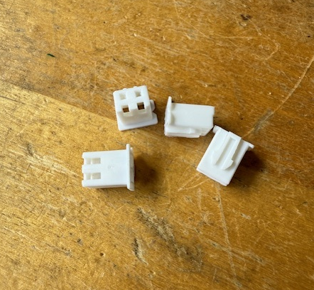
To ameliorate I came up with a simple bodge--using 100 mil edge connectors and shrink tubing:
..............which ended up looking like this:
It would have been more elegant to crimp JST-XH 100 mil connects to both sides of the jumper cables but at this early prototyping stage this workaround was good enough.
WHAT NEXT?
The 3 PCB's specifically for the project--jacks board, front panel, and concentric pots board--could be improved in terms of layout; also I had a few ideas for making modulation bias adjustment--needed in some cases for a nice smooth stereo pan at audio out--easier to tweak.
So....I will create revisions of the 3 PCB's, rebuild this in the coming weeks, and, if there is love, post it all on
PCBWAY's community site.
I already have the "version 2" boards laid out.
I figure they will WFT? We will see. Stay tuned!
 |
| AI generated background--hours of fun! |


