Readers: this is a work in progress but you can get the files associated with this post from Github, here. (Update--Euro 'version 2' of this module is working, post is here). ===========
Back again!
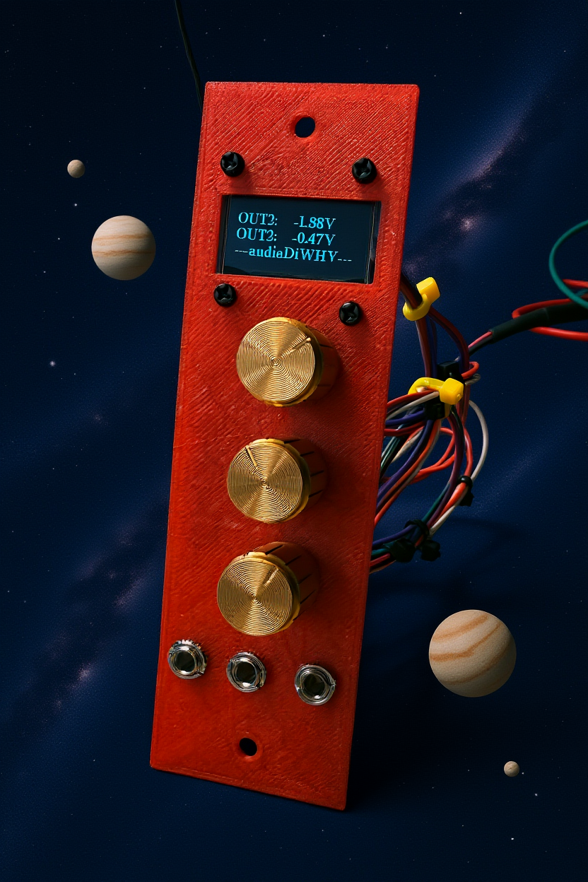
I wanted a synthesizer module that accurately output and displayed 3 independent control voltages ranging from -10V to 10V DC.  |
| The early prototype used a 3D printed front panel conforming to PAIA Frac format. Camera Synch issues meant my digitial camera couldn't capture all 4 lines of the working OLED but in real life it works. |
There were a lot of ways I could have done this--using a multiplexed bipolar digital to analog converter (post for DAC here; multiplexer here) but instead employed the 16-bit ADC features of the impressive ATTINY 1624 MCU, covered briefly in this previous post. Overall, design for version 0.1 was simple; I used the pots configured as voltage dividers, buffered by op amps, took the 0-5V wiper voltages from the pots and connected that to ADC inputs of the ATTINY, and had the MCU feed a 128 x 64 OLED display to convey the 3x voltages.
Finally I used inverting op amps to get 0-5V DC from the pots to the -10 to 10VDC needed at output:
 |
| One of 3 identical buffer subcircuits. A simulation of this simple inverting buffer/amplifier can be found here; I have posted the files for this prototype at Github, here. When the design is further along I will post files to the PCBWAY Community. |
CONSTRUCTION
I laid out the design in KICAD 9 and used Arduino Sketch to (quickly) create the firmware. Because the ATTINY isn't blessed with buttloads of flash memory I used Bill Greiman's memory-friendly SSD1306ASCii library (here) to provide functions needed for the OLED.
I sent the gerber file to this blog's trusty and most-excellent sponsor, PCBWAY. Very soon the boards were back. They do great work! You can help out the blog by checking them out here.
 |
| The prototype used 1206 SMD components, a stencil, and a Eurorack formatted front panel. After years of trying different workflows, this combination seemed a decent mix for fast prototyping, flexibility in terms of modification, and small size. |
After unbagging and inspecting components I discovered a major mistake: the PCB was too tall to fit into a Eurorack or Frac enclosure:
I contemplated pitching the entire thing and starting again, but instead consulted the guys in my audio geek discord group. Could this be fixed? No, but, one member suggested I try to build it anyway, to shake out the first batch of mistakes, before going to Version 2. Good idea....
I got building....
 |
Used my $35USB hotplate for SMD, works great.
|
 |
| Original design incorporated Eurorack power, but I adapted this to Frac Power using edge connectors, 22 gauge hookup wire, and shrink tubing. This allowed a fair amount of twisting and bending without breaking wires or shorting connections. |
 |
| Same idea for the rest of the hookup wire.... |
 |
| Initial tests showed way too much current draw for the positive rail--should have been more like 4-5mA, but here it's 230mA. I pretty quickly traced this to a 78L05 regulator being installed upside down, due to using the wrong Kicad footprint--I used the 3N3904 footprint, not 78L05, so Pin 1 and 3 were flipped. Whoops. I pulled the 78L05 using a Hakko FR301, flipped it, and resoldered. Surprisingly this snafu didn't blow up the MCU, nor the regulator. |
 |
| With the power problems sorted, things seemed to work--albeit not terribly accurately -- off by as much as 5% at times--but OK for the first attempt. |
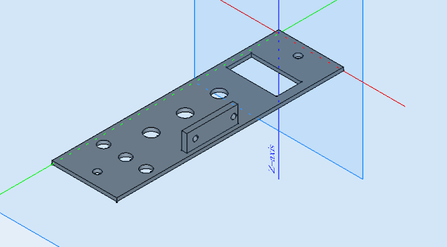 |
| I laid out a quick-and-dirty front panel for the PCB using FREECAD 1.01. |
 |
| Version 0.1, unpowered, in the flesh... |
 |
| Version 0.1 seen through the lens of open source AI (ComfyUI + Flux Context Dev with a 12GB Lenovo/Nvidia RTX2000 GPU). This first and only pass through the AI algo took 50 seconds and beat the holy crap out of what I could have done with an hour of organic intelligence and Photoshop--if this doesn't scare the hell out a tech + graphics professional, I don't know what does. |
OK, quick post but enough for now. I will keep plugging away at this project and hope to have a revision with better accuracy in the coming weeks. Update 8-28-25: Eurorack "rev 2" version of the generator is complete and works....please see the post here.
So--until next time: don't breathe the AI.