Tape Deck Mult Panel--An Easy One (Two)


Nothing like finished panels....


I guess I like the Tascam SS-R220 stereo solid state recorder....I own three of these....
What is good about these?


  • Good bang for the buck
  • Decent A/D D/A without paying a fortune
  • Digital IO so you can use better D/A if you want (I use a UA 2192 and one of these for mastering--always liked the way the 2192 AD-DA sounded).
  • The SS-R200 RCA inputs accepts synth 5V P/P signals without a lot of fuss
  • Good, easy to use front panel UI
  • Good manual
  • Works on SD cards, which are cheaper (and taste better) than a Big Mac
  • Remote control with a long cord (hey!)


In other words, someone at Tascam did good work on this one.


So what does this have to do with DIY?  I want to do sound on sound, 2 of these in one rack, so I figure I'd build a couple of quick mult-panels to accommodate, with some normals etc.

After sleeping on it, bingo, I know how I want to do this.

Hand drawn wiring setup (rear view) looks like this:


I use 3.5mm "normalled" TS jacks for my DIY work--I had to choose something, and always thought on the ARP2600 this was a good combination of size, convenience, and ease of using normals.

I already had about 6 unpopulated alubase panels I got from PCBWAY.

From here building 2 of these was easy work.  After mounting jacks and soldering up the mults and normals, I cut the one end off a couple of junk RCA stereo cables I had and used the cable and remaining males.

Here it is in my Fracrak:


Still need to label the panel, using Lazertran, but I am finished with the artwork already:

One of those things that's fun and easy.  


OK off to put some guitar parts through a Balanced modulator.  I'll have sound samples soon.  Really!


Getting started with AudioDIY and the Atmel ATTINY85: What to do with these tiny things?

UPDATE!: I have written two additional posts (so far) about ATTINY:

Pros and cons and debugging here.
Arduino Interrupts using ATTINY85 here.

OK back to the original post:

Hello Again! I can't help but be seduced by an Arduino that, from about a foot away, looks like an op amp. And costs only a bit more!!!

I'm talking about the ATTINY, which in its "85" form looks like this:


Can we really pack an Arduino punch into an 8 PIN chip?

Time to find out!

I bought a few of the ATTINY85's ($2-3 for DIP, good for prototyping; under a dollar US for surface mount) and a Sparkfun programmer for about $15 from Amazon:
From my reading, programming ATTINY using the Sparkfun is pretty straightforward--I figured I'd have the LED blink app up and running in 10 minutes?

But it didn't work!  10 minutes became a couple of hours....

Hello?

I have 2 computers I use for Arduino programming on my bench and the Sparkfun programmer didn't work on either: an older MacBookPro running OS-X Mountain Lion and a Lenovo T430 running CentOS 7.  I have used both many times for programming Nanos such as the one used for the SynthDMV.

After following the Sparkfun instructions (which are very clearly written--good work Sparkfun) several times, no go; it's like the system couldn't find the ATTINY85 chip I had put into the programmer.

Driver issues?

Many documents on the web say for Linux and Mac you don't need drivers for this Sparkfun Programmer--only for Windows and thankfully I don't do Windows in my electronics lab....too much Windows at work, don't need that here as well!

But still it felt like a driver issue.


Lots of head scratching....odd that I saw this "hide the ATTINY" issue for both laptops (different OS's right?  different hardware)?

To make a long story short, I found other poor sorry fellow dumb SOB's who had the same problem, and one of them suggested "try a different USB cable".  Well, I wasn't using a USB cable at all; I was just plugging the programmer into an open USB port of either laptop.  Seemed at best like a long shot but after 2 hours of messing around with this I was ready to try anything.

I dug around in my USB cable crapola box and found a M/F USB 2.0 extender--a standard M/M USB cable wouldn't work--I plugged the Male into the Mac, the Sparkfun programmer into the female side, and of course after that the programmer worked!

Now that makes no sense at all....i could see the programmer being unhappy with the USB port on one laptop, but not two, and running different OS's at that--and it didn't work on any USB port anywhere, but with the USB extender cable it worked everywhere.  Makes no sense!!! 

I posted this on an Arduino Forum and got zerohttp://forum.arduino.cc/index.php?topic=388043.0 responses, so maybe of the 7.7 billion people on the planet I'm the only one to have ever have had this problem?  Whatever.

UPDATE!! FIGURED It OUT! It had nothing to do with cabling, drivers, or anything else. both the mac and linux machines are linux based and both weren't giving the programmer permission to program. I still don't know why the system worked after I changed out the cable, I must have done something else (run arduino IDE as root?) total mystery until I found this. Here is how to fix this issue:

  • From your linux box, open terminal 

  • issue the command 

lsusb

  • note in the list which one is TINYUSBISP: for me it is this: 

Bus 003 Device 030: ID 1781:0c9f Multiple Vendors USBtiny

  • now issue this sudo command where the last 2 numbers match bus and device numbers spat out by the lsusb program. 

[clamm@localhost ~]$ sudo chmod 666 /dev/bus/usb/003/030


fixed!

Onward!! Anyway: now that the BLINK proof of concept is working--a few things to think about:


  • There is no "official" I2C library for the ATTINY.  I see folks using this "BroHogan" i2c library; I have yet to test it.  So my favorite I2C goodies like the MCP4725 D/A are not supported using the more familiar wire.h library, but that's probably OK.
  • SPI is the same deal--but you can apparently use this guy's software to do SPI with this chip.
  • There is a LED on the programmer--D0--that does help a bit I guess.
  • There is no built in serial I/O in this system, which makes debugging harder.
  • You have to supply your own 5V power supply--to power the chip as well as any peripherals--there is no 5V regulator on board, as there is on the nano.
  • Tinkercad Circuits, which I use all the time to bang out virtual Arduino code to then use in the real world, supports ATTINY. And from messing around with it so far: at least some of the slightly more arcane features, like Pin Change Interrupts, appear to be supported.  yeh!!!
  • The Programmer you see above has breakouts for the pins on the ATTINY--so you aren't schlepping the chip in and out all the time--very useful.


OK time to put this on the bench:


Yes, blink works, analog in works, basic interrupts work, and so on.

After an afternoon of messing around, two designs came to mind that might be good candidates for projects based on this chip:


CMOS 4051 based CV selector based on incoming control voltage:


The CV is read by an analog pin (need to condition the CV to be 0V < x <5V, but that's not too hard) and then used to switch between CV fed to 4 or 5 of the 4051's inputs.  Any audio would have to exist between 0 < x <5V as well, but if you can massage the audio to that range, that should work as well.  That's all simple op amp stuff right?


Update!  I have this 4051 switcher working in a simulator, read about that here--the 4051 business is at the very end of the post.

Or, a low parts count (I think) trapazoid generator:

Hope I am not using too many IO pins here!

Overall though I keep going back to this nagging thought--why not just pay an extra $4 or whatever and use a nano clone? You get more pins, more options, serial for debug, etc. Of course the Nano is bigger, but not too big for projects that involve 1u Fracraks which is the smallest thing for which I'd probably use Arduino.

So I am left wondering what if anything AudioDIWHY I will use ATTINY for? Guess time will tell....

BTW I think these guys are burning audio stuff onto ATTINYs and selling them as finished audio DIY chips.  So the tenement version of a VLSI chip making operation. Just a guess? Makes sense--and if that's what they are doing: clever.

Regardless it's cool that fellow hackers have made an Arduino IDE-ready chip that's this small.

OK that's it.....Until next time....as always, don't breathe the fumes.

Mad Bees! Avalanche Ramp Oscillator--Smells like Insect Spirit


Greets again fellow synth nerds:

I broke my own rule of DIY and perfboarded a new design. The rule: I figure it's quicker these days for me to use Eagle to craft a PCB I want to mess with, kludge in any parts, and see if I can get it to work. If I can great, if not, toss it and start over....but not this time....

The back story?

I was up late watching my usual youtube electronics vids to help me fall asleep (Carlson's lab is a favorite for that! 2+ hours of a Canadian tech saying "abooot" while restoring a tube amp? This guy is awesome!) and came across this Colin Furze clone DIY audio dude. At least he's a synth player, he doesn't ride around on jet powered bicycles and you gotta love that earring!

Close enough!

OK Sir Thomas Dolby-Colin Furze's kid brother has a super fun series of vids about using a NPN as an "avalanche oscillator".  (BTW I really like his videos! All kinds of great stuff! Mr. Carlson's energy and then some! Ah...to be young again...Like, subscribe, comment + notify, you know the drill)

I have seen avalanche circuits using zeners but not this.

His design (he probably borrowed it?) was so simple I literally jumped out of bed and bread boarded it. 1AM!  And I had to work the next day. Yow.

Oh yeh, There is a big-butt mistake in his first vid--what you get for "You can skip this ad in 5 seconds".

LookMum shows a pink explosion schematic with the 3904 upside down--being British he was probably using a BC series--yep pins are flipped, but otherwise, once I caught that, it worked.

The next day I perf'd it.  Hours of fun....

here is the schematic I ended up using for my perf-non-masterpiece (?)--a bit more complex than what LookMum shows....and BTW my circuit worked with the 3904 center pin not cut off...but who cares?


As this Sam LookMum says, you need to mess with the LED's to get different sounds, by George! I used 3 LEDs, a flame LED (you know, it flickers, used in fake electronic candles), permanently wired up to the 3904, a small green LED, and another flame LED. A single switch controls the outer 2 LED's.  The green LED, when goosed with the right right frequency, sounds to me like a bee! Bugger off mate! For the other two I labeled them "worker" (audible random burps) and "queen" (nastier bigger/hairier audible random belches and burps).

Another minor detail Sam lookmum doesn't mention: if you perf it up his way, unless you invert the CV, higher voltages lead to lower pitches--but who cares?  I stuck my CV through an op amp inverter (right-side up bee on finished panel) as well as not (upside-down bee). Whatever....

For those playing along at home, here's a youtube of the nearly finished circuit at work....


And--Here a Soundcloud mp3 I did in about two minutes--it's just different bee samples recorded directly to a VCA and out to my DAW, multitracked then mixed together with some reverb.  If I can do this in two minutes, figure what you can do in 5!

The obligatory "circuit on the bench" photos....


Here's another.


Done! I already had a front panel from PCBWAY left over, so this was easy to finish. decal'd it using Lazertran....bolted it into my Fracrak, next to the random gate which is a good CV source for it.


What next? I  have already designed a PCB for this, it would be fun to do 3x or 4x in a dual gang FraCrak panel, sort of what I did with the 40106 design for the Lunetta VCO.  But then I have to get it fab'd then test it, one of these days?

This is a super easy and fun DIY circuit, highly recommended!  Until then don't breathe the Canadians!

Arduino based SYNTHDVM--Up and Running.

Hello again, yes it all works.

The SynthDVM is as far along as I think i will take it.

For anyone who wants to catch up:

Part one is here--as I try to master the art of undocumented Arduino clones and parts.

Part 2 is here--Design goals for the project.

Part 3 is here--Let's get the OLED meter to look "analog"


Part 4 is here--  clobber that op amp!

About the DVM, It reads DC from about -10.5 to +10.5V with an accuracy of better than 1% throughout its entire sweep--very close to .5% for say 5V and pretty much dead on between +/- 3V.  As they say (I say)  in audio DIYland "good enough".

If I designed a custom PCB for this, which I see little point in doing, with a good layout and large ground plane, it'd probably perform better but it's not bad for a sandbox PCB, a nano, and a handful of op amps.

There were some evenings of cursing over this one, I had some ripple on the op amp + and - rails I couldn't get rid of, but I finally re soldered a few traces here and there and now it's fine.


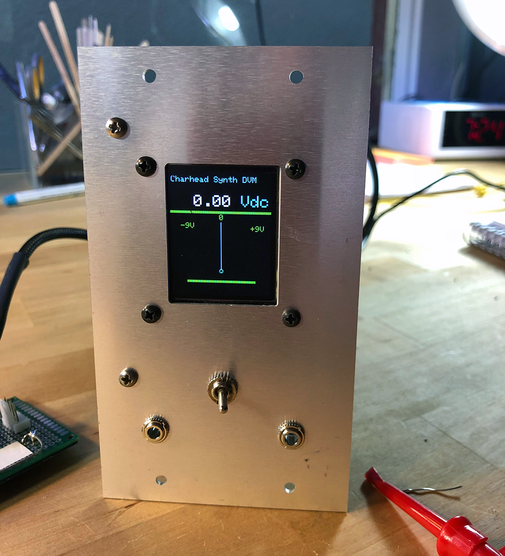
I haven't got the artwork for front panel done yet, but that's coming soon I hope. The front panel is completely simple: the left jack is input; the right is signal thru. The switch chooses between AC and DC at input.

Yep, I decided that I wanted to measure the amplitude of audio signals as well as CV DC. To get that done I used an AD736 RMS converter chip, which is so easy to put into your projects it's almost funny.

I copied the AC to DC design I used in the DVM straight out of their app sheet (page 13).  Yow.  The switch hits a digital pin on the Arduino and tells the arduino to read the output of the AD736 vs. the op amps that are running DC. Simple!

More features?  It's software, why not? If anyone wants to take this over, it'd be cool to have the switch throw an interrupt (or whatever) and redraw the needle graphic as a VU meter, since the RMS will never read a negative voltage, but I am tired of working on this one and need to move on.


From the build...I built up the DC part, tested it working, then bread boarded the AC-RMS sub-circuit on the trusty Radioshack learning  lab (circa 1977--still works great--and I didn't know this but you can still get them!).  After I got that working--easy--I moved all the parts to the circuit.


I used the PCB you can read about on my website for all the op amps, the Nano 10V regulator, as well as the Arduino Nano itself.  Also if you are thinking of building this or something like it, please take a look at the schematic and build notes PDF. You can review the code on Github and I'd also suggest looking at my last post about this to read up on a cool "clobber the op amp" trick which I think is useful outside of just Arduinoland.


What next for cslammy and Arduinos?  Who knows?  Until then don't breathe the fumes!

Synth DVM part IV: Neat Arduino Trick--good for Audio DIY--Crush that op amp!

I finished (!!) my arduino based Synth DVM, it worked last night anyway; need to do a few final software tweaks then will post.  As always I am sure someone can improve it, but it's working well.

You can see part 1 here--I try to master the art of undocumented Arduino clones and parts

Part 2 is here.  Design goals for the project, Blah blah ginger blah blah.

Part 3 is here.  Let's get the OLED meter to look "analog"

How it looked about a week ago...front panel an "alubase PCB" from PCBWay....the PCB is already bolted on. Along the way I found a cool and easy way to make an Arduino treat audio like it's running through 4066 cmos switcher. Maybe better?

It's a nifty enough trick that I thought it should have its own post.


My DVM.  FracRack panel.  It's actually done and working now.../


The hack goes like this:

If you've screwed around with Arduino for more than a few minutes you find the things don't like negative voltages w high current on their analog pinssince my SynthDVM is chock a block with negative voltages--it needs to read negative voltages relative to ground, I had to deal with this.  OK....

As long as you're careful with your design, carefully incoming limit current, we're fine, there's diode protection in the Arduino analog pins, but what if we're not fine?

Just to be safe, negative voltages at analog pins should be designed out if possible?

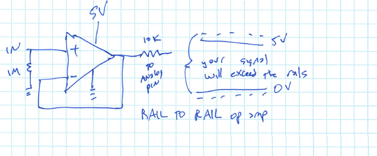
There are many ways: use an op amp in front and use GND for V-- and 5V for V++


But this will chop off some of the upper voltages close to 5V and voltages near Ground.  Not good for a DVM!

Or block the negative voltages/reverse bias current using a diode....


You'd still have to figure out a way to limit the upper voltage since Arduino pins don't like to see more than 5V relative to ground, maybe use a zener for that?  

But for a DVM this is a non starter--the output voltage sees a "diode drop" of .6-.7V which for a DVM application probably isn't good--we want incoming signals to be as unadulterated as we can. And diodes are temperature sensitive....

How about a rail to rail op amp?  I probably could have made this work, but I fried my last R-R op amp on the bench working on another project--oh well. There is also the consideration that many R-R op amps allow signals over that can go above the VDD, but I figure Arduino can probably roll with that.  

Thinking about this project, I should have just bought more rail to rail op amps--yep I should have dug into this idea more.  It probably would have simplified the design a lot. Something for a future post.


AC couple and then do an DC offset?  That would have limited my measurable signals to something like +/- 7V by my calculations, and from +/- 15V supply I wanted to be able to measure more like +/- 12V.

There are lots of ways other ways....

I discovered a way to do this by accident: you can use Arduino digital pins to clobber an analog signal, negative or positive, as long as it is less than say 30mA (as I read the Atmel datasheet, it's 40mA, but let's stay far away from that....)

So how about this hack:


You still have to protect things to not go over 5V--I used a voltage divider as you see here, which for me worked fine but if you're really concerned, perhaps use a zener to limit the top end to 5V.

For an inverting op amp, it's the same idea--connect the output pin to a digital pin on the arduino and suck the signal out of the op amp to ground.  I think I did this something like this, I will post the final schematic soon:


R1 limits current to D3, so that's important (!) and R3 limits current through the op amp--so be careful with these values.

Now program your arduino like this:

      pinMode(3,OUTPUT);
      digitalWrite(3,LOW); // PIN3 is now a working ground. Send a signal destined to go to A0 to ground; so we clobber analog signal to A0

(or)

      pinMode(3, INPUT) 

D3 goes high Z, op amp unaffected; signal delivered to A0 just fine.


So that means that you can use this trick to turn on and off analog signals as you would (say) a 4066 or 4016 cmos switcher. Output/Low the signal is off.  INPUT, the signal is on.  Easy!!!!

Cool! I didn't think it'd work but it did! 

Questions:
  • Do I think I made this hack up?  Nope. If there isn't documentation about this hack somewhere else already, I'd fall off my chair, but for the 2 cents it's worth I couldn't figure out a way to google it. Whatever. 
  • Can I flip/flop pinModes every x milliseconds and not screw stuff up?  Yes. It seems to me like flip-flopping pinModes very quickly--input to output--and back--doesn't phase the ardino at all. This surprised me, but for my design here, nope it wasn't an issue. I haven't totally tested this vs. say a 4066 for "what can flip faster?  What "sounds better?"  Don't know. Put it on your bench, fool with it, and let me know!
  • Does this work for clobbering audio signals that are more than say 2.5V P/P?  Yes. I could power my op amps from +/- 15V supply, run an audio signal to close to the op amp rails, and still use the above hack to clobber the signal.  Just make sure you are careful about resistors like R1 and R3 in the inverting diagram above.  We don't want to send too much current to the OUTPUT/LOW pin, or the A0 analog pin, and we don't want to heat up the op amp but not limit its output either.  But as long as you can work with that, we're good.
  • Does it work for positive or negative V relative to ground?  So will D3 in output-LOW mode source and sink current? In rapid succession? Yes.
  • In this application, does this work better in this app than a CMOS switch (4066?) for me, yes. 4066s just don't work well with voltages below Edison ground. There were other ways to do this, for sure, but this worked.
OK More on the entire DVM project soon, I am pretty much done, just need to finish the documentation. I am pretty happy with how it came out....and that I stumbled into this OUTPUT/LOW INPUT hack along the way!  OK enough until next time: don't breathe the fumes!


40106 Quad opto coupled VCO--Lunetta Lives!

All hail Lunetta Synthesis--the CMOS anything-goes way of thinking about Audio DIY?


One thing that appeals: Stanley Lunetta is from the California Central Valley, same as me--from my reading his studio was about 40 miles from where I was recording back in the day.

Does this prove that we Central CA folks aren't all farmers and politicians?  Does it need to be proven? Growing up I remember a great music scene, at least in the 70s. Makes sense--there was very little else (legal) to do!

OK: In honor of Lunetta Synthesis and all Central Valley artists I decided to fab a quad VCO using one of the great CMOS chips, the 40106.

I've messed with this chip before but this was my first attempt at doing something this, well, VCOish.

I went through a few generations of experimenter boards by designing in Eagle, and sending off to EASYEDA for a test fab.  I almost have given up on perf'ing things. It's faster and easier for me to have boards fab'd abroad, sent back to the US, and if they don't work, try to kludge them into operation or just toss them and start over.

OK, the board I ended up using for this is here (on my website) and tests working.  Yeh!


Here's the schematic....you can get a zip of this in Eagle format on my site.


Ok so what is up with R1, R2, R3, R4?  You can use the values in the schemo above and call it a day, but what fun would that be? Instead I replaced these resistors with optos: four optocouplers bought surplus from Electronics Goldmine, but for this design go ahead (!!) and use whatever vactrol or pot or resistor or thingy you care to use. Or just use a resistor? Try different things. See what you like. Experimentation is the key here, have fun!!!!

Using the optos, I could get pretty decent (but highly non-linear) output from LFOish, maybe 2hz? to about 12K and up.  Good enough for F/X.

EZ buffer circuit fragment used for the optos

One thing to keep in mind: the 40106 is a lot of audio for the buck but in reality can't hold a pitch to save its life. Any temperature or current variation--even a slight one--drives the output pitch crazy. Even power cycling the chip can change its pitch for a given RC value. So it's no substitute for say an ASM VCO.  But for effects and noisemaking, it's just fine.

About the goz-outtas: This is a bit un-Lunetta but I wanted to get the output waveforms 10V P/P or close. So I also incorporated some quad TL072 based buffer boards I have been messing with for a few months. I will try to post more details on my website soon but this is four of the non inverting op amp gain stages you can find on my website fab'd on one PCB.  

I had to go through a few generations for this--the first gen had a bozo mistake with how I laid out the resistors, but what is below worked.  I have already designed Gen3 with a more logical layout for the resistors which are all over the place in GEN2.  this is the world of easy PCB prototyping?

This is basic op amp stuff, but the quad non-inverting board can be used to take four different CMOS type signals and turn them into say +8V Peak to Peak with a 4V DC bias offset.  Since you have to buffer the triangle out of the 40106 I had to do something like this right?


UPDATE.  It makes more sense power supply wise to use inverting stages w bias offset vs. what I have below. The boards will draw much less current!  I have information about a more power efficient board in the BOWAL project and on my website--if I built this again I'd use the buffer/bias circuit here.

"It even does FM": Another interesting thing: it's way easy to add FM to this. Add a diode reverse biased and a 1K resistor in series ahead of the RC that sets pitch and then feed it any audio signal above maybe 2V P/P for um.....interesting results.  I will try to post some bleep-bleep sounds but for me this is hours of fun.

In other words: take this fragment and put it between your audio signal and the FM1, FM2, FM3 etc. inputs you see on the board.  Does it get easier?


Some build photos......

Finished module, still need to do front panel artwork.  

Perfland, easy way to make a few small boards into one big module
OK time tor record.....in case anyone wants to see more here is a zip of the entire design pdf.  if anyone has other ideas about this please comment, I'm always up for seeing what others are doing in 40106 land.  And I will try to add sound samples down the road.  Don't breathe the fumes!

DIY Synth and Electronics Pseudo Silkscreening using "Lazertran"--How To Do This!

Several years into the DIY thing and I still trying to figure out how to make low-cost, low quantity, high quality front panel silk screen art.

Still can't solve that one!

Update! I am using Front Panel Express as well for this--see the post here, it's about $40-50 USD for a single 1-U Frac, that's not what I call low cost, but they make great stuff....

Instead, I have been using a water slide decal process to get me close to silk screen type front panel finishes using something a decal process called "Lazertran".

That's what this post is about.

No, I don't work for these guys. This isn't an ad or promotion. This is however the best way to make low cost one-off front panels that I have found to date. it's $1-$2-$3 USD per panel, pretty affordable.

Still with me?

Next, go out and get this stuff: "Lazertran." You can find it online direct from the manufacturer, also at Blick Art, Amazon, and several other online suppliers. Your local art store may also have it, or maybe can order it for you. As of 12-16-19, with tax and shipping it's about $3USD per sheet.

There is one Lazertran version for laser printer and another for inkjet. Before you Begin! Make sure you have the right printer. There is a list of printers that work on the Lazertran website in the faq section, go here. Hewlett Packard B+W printers (which is what I have) supposedly all work; mine does. I have also read (here) that older Lasers work better than newer ones.

I set my HP 402DW to "heavy paper 130g" so you set up the printer to use card stock; your printer might be different. Lazertran is a bit on the thick side so set your printer accordingly.

I only have tried the process here with the laser version. You can get legal sized sheets or 11 x 17 but here I use 8.5 x 11. I'm interested in knowing if the inkjet material works the same way as described below, if you know I'd be grateful for comments.

Before we go on: the required safety stuff. Please be safe! This process involves putting paper and metal into an oven and cooking it for a few hours. You have to be sensible or you wouldn't survive a week of DIY.....So please, don't be a bozo about this--be careful while handling hot materials, you could burn yourself.


In addition to staying safe, you will also need:
  • The metal front panel you want to use, ready to go. If you've painted your metal panel, make sure it will withstand a 250+ F degree oven bake. So, high temperature paints, like those used for car engines, are best. I leave figuring out the right kind of paint to you.
  • You'll need an oven that goes to 300-350 degrees F. Most of us have those, or use mom's? Whatever. I imagine toaster ovens will do as long as you can control the temperature.
  • Scissors to cut out the decal. 
  • Computer software to design, modify and flip your decal--Adobe Illustrator is what I use but there are lots of programs for two-dimensional artwork.
  • Tongs or BBQ implements to handle your panel when it's hot.
  • Paper towel for smoothing out tiny bubbles
  • 800 to 2000+ grit wet/dry sandpaper.
One more thing: all the temperatures in this post use the Fahrenheit standard. I know it's downright colonial for me to do that, many of you use Celsius, and most of the time I try not to be a stupid American who thinks the world only exists from Hawaii to New York. I didn't want to constantly post 2 numbers. If needed Here is a good site to translate between the 2 standards.

OK let's go:

Prepare your metal work. For Lazertran decals to look decent, your front panel has to be extremely smooth--the decal will tear and hang up on any burrs or rough edges, form bubbles over oil and dirt, and generally look crappy. I thoroughly wash the panel with dish soap, then sand it with 800 grit wet and dry sandpaper, then a 1200 grit sanding pad then wash it again.

Next this may be obvious, but: take careful measurements of your cleaned up panel. If you mess up your measurements you will have printed a $2-3USD Lazertran decal that won't fit your panel, and we don't want that.

If you really don't want to measure things: I have used a Ricoh flatbed scanner to scan a 1:1 image of the front panel(s) in question; then used the PDF output from the scanner as a background in Adobe Photoshop. Before printing I hide the background layer. As long as the original scan is really 1:1, this will work.

Another way: I first draw the front panel in a CAD program (Eagle in my case) to create a down-to-the-millimeter drawing of anything that needs panel art. Save it as PDF or PNG and then use that as the background in Illustrator or whatever graphics program you use.

Eagle BRD file of a Fracrack 2u panel

As long as the elements you see in the background are holes, drills, dimension layer outlines, and mills, they won't show up in the final panel, but can be used to design and align the decal.

About color decals: If you are doing a color panel you're in territory unfamiliar to me, I only do B&W, but keep in mind that almost all inkjets can't print white and I don't see that Lazertran is supported for most or all color laser printers. B&W printers assume the background is white and treat white artwork as clear so it can "show through".

I imagine from model making that CMYK colors may appear a bit faded or washed out so flat white paint on the panel before decaling may help. Just a guess.

ENOUGH ALREADY!  LET'S MAKE A DECAL!!!!

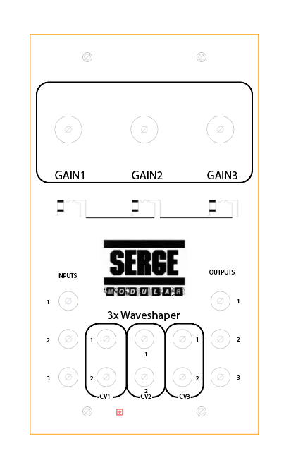
For this tutorial I am fabbing a new one-off panel for a Triple Moog-like VCA clone for which I did a PCB board design, as well as the GCS/EFM/everyone-else Norton 3900 amp based Serge Waveshaper (hence the Serge logos--give 'em credit where it's due--this is a really cool bit of electrical engineering on Serge Tcherepnin's part--you can get details, boards, gerbers etc. for it everywhere, my version is here....

Here's what I ended up with in Illustrator for the Serge module:

Before printing to your Lazertran decal paper, check your printer settings, print out a 1:1 of your  artwork, and lay it over the panel to see if everything lines up--you want to do this with normal paper before committing to Lazertran.

Here I've done that with cutouts of standard 8.5 x 11" paper--yep looks OK.


Now go back to your art program, select all the elements in your design and flip things, so it's 180 degrees flipped along the Y axis, like this:


Save the flipped file--we are going to need to print the flipped decal image to Lazertran.

OK, here's a semi hidden secret. You have to BAKE THE DICKENS out of the Lazertran sheet before you take the decal off the backing. Otherwise your decal will bubble during the baking process.  

The Lazertran docs say to use a hair dryer, but I use my oven as I've had better results. For this pre-bake-your-decal-sheet process, preheat your oven to 225 degrees F. and then put in the decal for about 6 minutes.  

Stink it! As the decal bakes you may smell a gross plastic burning smell. Sorry. And when you take out the decal paper it will look like you tried to BBQ it:

Update: I have gone back to using a heat gun for this. Specifically I am using my hot rework station to bake the decal vs. the using the oven; 3 minutes of blowing the rework nozzle at the decal at 475 degrees seems to do the trick. Probably not what Sparkfun thought of when they put the HAR device on the market?


Charred Lazertran.  Mmm Mmm stinky!

The good news is--I learned this by trail and success??--the decal will still look OK even though the backing paper got charred. But you can over bake the sheet....then the decal won't come off, so keep checking on your decal during this pre-bake. I have best results when the backing paper is charred to about the point you see in the photo above.

Next, cut out the decal along the panel lines:


if you can, cut out each drill a bit larger than needed (say 100-200 mils)--you will get less bubbles if you lay decals down on flat continuous metalwork vs. having them covering up drills.

Then soak each decal in warm tap water for about a minute--less if you can. Warning: Soak for as short a time as you can; if you soak the decal too long the decal may start to disintegrate.  I have seen this on occasion, but other times I have left the decal in the water for 5 minutes without issue. No idea why. 

UPDATE: I finally figured out what the issue is with disintegration! 

Since about mid 2019 Lazertran put a protective opaque coating over the "decal side" of their decal paper. You need to peel off before running it through your printer.  I was having about 30% failure rates with disintegration and I couldn't figure out why. 

After looking at the failed sheets under a microscope I discovered removing the opaque protective sheet was also removing the decal material itself. The two look alike so it's hard to tell! So: Be super careful when removing this protective sheet. 

The decal material has a slightly matte/bumpy look when you first peel of the protective layer, but becomes shiny after the "heat the decal" process described above. If the decal doesn't get shiny when you heat it up you probably removed the plastic decal material by mistake; and your decal will be butt and disintegrate. Face!.


I didn't get a photo of this, but apply the flipped decal face down to the front panel by sliding it off the backing and onto your front panel.  

Line it up carefully.....

Now you've got to get rid of the air bubbles that invariably live under the decal you just applied. 

I have tried all different ways to "de-bubble" but the best way, the way I always come back to, is use my fingers to get the big bubbles out, then gently (!!) use a credit card edge to wisk away all the smaller bubbles. You will probably have to re-position as you go, that's not a problem, be gentle so you don't tear the decal.  

Again no photo for this--I was too busy trying to not ruin the decal and get rid of all the bubbles. But with a gentle touch it's not a problem.  

Hold the panel up to a light and see if you can see bubbles under the decal. If you can still see bubbles,  repeat the process.

Last step before the bake, take a napkin or paper towel and carefully dab off whatever water remains on your panel. Then check for air bubbles again.

Once you're bubble free it's time to bake the decal onto the panel.   

ON TO THE PREBAKE--GET THEM BUBBLES TO BUBBLE, RAWHIDE!

Preheat a cookie sheet to about 225  degrees and before the initial bake, remove the sheet and put it on your counter.  Then, put the metal panel w/ decal face up directly on the sheet. I have seen some bubbles I missed immediately bubble up at this point. They can be pushed back down with a quick stab with your fingers. Yes, a 225 degree metal cookie pan is hot , so be careful, but this "prebake, prebubble" step is completely essential.

BAKE THE DECAL AND METAL!

With the decal now fully debubbled, set you oven to 170 F and put the decal in there for 2 minutes.  

Important: After 2 minutes remove your cookie sheet, and check the panel and make sure bubbles haven't formed.  If you have bubbles at this point you can quickly touch them to flatten the bubbles or pop bubbles with a pin, thus repeating what you did in the "Prebake."

After about 10-15 minutes the big ones are with you to stay.....so set your timer and do this check.


(I have done Lazertran bakes in a pan, on tinfoil and on a cookie sheet--after trying different things, baking on cookie sheet seems to work best....)

After the two minute check, try another check at 10 minutes; after that you're past the bubble popping stage. 

Keep the oven at 170 F for an hour (if you are impatient, half hour will do, but the more time you bake the better the decal looks at end), then 190 F for an hour, then 220 F for an hour. OK, 250 F for an hour, finally 275 F for an hour.  

Don't go over 275--the decal might burn if you do.  Not 100% sure about this--I have gone to 350 F without issues, but other times going above 275 will make the decal turn brown.

When all this is done, remove the cookie sheet from the oven, and let it cool.  Next remove the panel from the sheet with your tongs. After your 4+ hour bake, if everything went OK, you end up with a pretty darn good looking panel, not quite pro silk screen looking, maybe a few blemishes here and there, but close.....with some practice you can get really close.  

Look Ma! No Photoshopping!....if you are careful with lazertran the results can be very clean.


And after a full bake if all went well, the finish is really baked on--I have had difficulty removing the decal with 500 grit sandpaper. Yeah!

For clean up, you may need to take an X-acto blade and get rid of any remaining decal material that's sitting over a drill, outline, or cutout. But for me after a few hours most of the decal that went over holes and milling has baked off. 

And....if you did end up with bubbles, you may be able to sand them off. If needed, I use 800/1000/1200 grid wet n' dry sandpaper to gently sand the panel to give it a more uniform look.  Don't be too rough--especially with the 800--but if you baked the decal on for hours it should withstand a lot of abuse.

I have experimented with clear coating, but am not sure that improves things any.

Here's what I ended up with while doing this blog post:


OK that looks pretty good I think! 

We're now ready to finish things.  Bolt on the PCB, mount pots, knobs, etc.

Here is how my Serge Waveshaper clone looked when I was done.


Not too shabby?  You can get very fine details out of this process--the "1", "2", "3" by the jacks is 6 point font and is fully legible, and the "normals" illustration below the gain knobs is even smaller but came out just fine. You get the idea.

One  more hint:

If you're in the process of fabbing your panel, you might try experimenting with baking on the decal following the process above and then drilling out remaining holes and mill work.  

As long as you drill and mill carefully--a skittering drill bit will tear the decal, screw up your panel and possibly injure you--this works better than drilling/milling then applying Lazertran. You can add x marks to your decal where you need to drill....this helps with panel symmetry and drill placement.  

OK that's it for now, give it a try and let me know what you think. I am always working on improving this process.