The SynthDVM is as far along as I think i will take it.
For anyone who wants to catch up:
Part one is here--as I try to master the art of undocumented Arduino clones and parts.
Part 2 is here--Design goals for the project.
Part 3 is here--Let's get the OLED meter to look "analog"
Part 4 is here-- clobber that op amp!
About the DVM, It reads DC from about -10.5 to +10.5V with an accuracy of better than 1% throughout its entire sweep--very close to .5% for say 5V and pretty much dead on between +/- 3V. As they say (I say) in audio DIYland "good enough".
If I designed a custom PCB for this, which I see little point in doing, with a good layout and large ground plane, it'd probably perform better but it's not bad for a sandbox PCB, a nano, and a handful of op amps.
There were some evenings of cursing over this one, I had some ripple on the op amp + and - rails I couldn't get rid of, but I finally re soldered a few traces here and there and now it's fine.
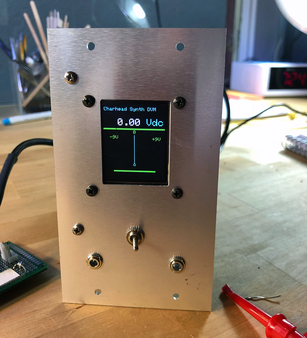
I haven't got the artwork for front panel done yet, but that's coming soon I hope. The front panel is completely simple: the left jack is input; the right is signal thru. The switch chooses between AC and DC at input.
Yep, I decided that I wanted to measure the amplitude of audio signals as well as CV DC. To get that done I used an AD736 RMS converter chip, which is so easy to put into your projects it's almost funny.
I copied the AC to DC design I used in the DVM straight out of their app sheet (page 13). Yow. The switch hits a digital pin on the Arduino and tells the arduino to read the output of the AD736 vs. the op amps that are running DC. Simple!
More features? It's software, why not? If anyone wants to take this over, it'd be cool to have the switch throw an interrupt (or whatever) and redraw the needle graphic as a VU meter, since the RMS will never read a negative voltage, but I am tired of working on this one and need to move on.

From the build...I built up the DC part, tested it working, then bread boarded the AC-RMS sub-circuit on the trusty Radioshack learning lab (circa 1977--still works great--and I didn't know this but you can still get them!). After I got that working--easy--I moved all the parts to the circuit.

I used the PCB you can read about on my website for all the op amps, the Nano 10V regulator, as well as the Arduino Nano itself. Also if you are thinking of building this or something like it, please take a look at the schematic and build notes PDF. You can review the code on Github and I'd also suggest looking at my last post about this to read up on a cool "clobber the op amp" trick which I think is useful outside of just Arduinoland.


What next for cslammy and Arduinos? Who knows? Until then don't breathe the fumes!


No comments:
Post a Comment