How much have I learned from Thomas Henry's books? Well it's all relative I guess, but for me, a lot! I went from zero knowledge about OTA's to well, some knowledge. Two of his books are both recommended if you want to learn how OTA synth circuits work: "Making music with the 3080" and "An Analog Synthesizer for the 21st century".
Each book features schematics for different VCO's. The former, 3080 based; the latter 13700.

If you've studied audio DIY for synths you've probably run into these IC's before; in goes (low) voltage; out comes current, and best of all, you can control the output current in a linear fashion (hopefully) with an independent "gain" current at a dedicated input.
But it's not quite that easy:
- The gain current input lives a diode drop above V--. So to make this go, you often have to use PNP Transistors which seems to me oddly counter-intuitive. Hello?.....OK....
- If you put too much current into the gain pin (2mA I think? 1mA? don't remember but it ain't much) you blow the crap out of the OTA chip. You don't get a buzz, a hum, smoke or whatever, it just dies and never works again--fast, like in milliseconds. OTAs are fragile!!
- And these damn things can be expensive to replace!
- The input gain control to output current is a linear relationship, but only for a narrow band. If you outside this band, it's distortion city. No, not 6v6 cool sounding distortion--really crappy ugly sounding distortion.
- The voltage at input needs to remain small, like 30mV? Don't remember that either, but it's not much.
The 3080 and 13700 OTA ICs are obsolete you say? Ha! you can still get 13700 clones from CoolAudio and I still see 3080s come up for sale every now and then on Ebay, Mouser, surplus places and the like.
I've now built 3 TH OTA VCOs as I write this.
UPDATE! Sound clip added. I find myself using the THVCO's a lot for FM type sounds. Because of their pure waveforms and large frequency range, they are very good for that. Sound demo is here.
About the VCO's: The designs aren't quite as simple as the ASM VCO but yield really good looking triangle and sine as well as pulse and ramp, with good stability, a wide frequency range (putt-putt LFO to way too high for me to hear), and good V per octave performance over about 8 octaves. TH probably put a ton of work into these designs and he deserves our gratitude.
Nice to have another 3 VCO's in my rack.
 |
| 3x THVCOs. Not fully labeled yet, but they all work. |
I still need to do the LazerTran phony silk screen to the left two units.
OK, Done.....

For all three: No mods really, except I had to change op amp gain at the output of the sine waves to about 4:1. What is in TH's books come in at about 1V P/P sine for everything I built. That's too easy. Easy fix: change out a resistor value in the output buffer for sine.
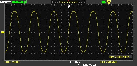
BTW the waves look really good on these VCO's!


Details on the fab: There are lots of ways to build your own THVCO, including buying PCBs from guys online (licensed sometimes, sometimes not?) who will gladly sell you THVCO inspired PCB's.
For me, I always fab my own boards (easier to mod, for one thing), but for this, a single printed circuit board using all through hole would have been huge--a lot of parts--and my Fracrak case is not that big, so I created a "motherboard" and then used 4/40 hardware to screw daughter boards (3 of them: CV volt/octave to log; OTA VCO core; waveform generation from triangle) to each one.
 |
| the boards lying on the bench are the motherboards. |
 |
| Dual concentric pots are huge spacesavers!! I get 'em from Small Bear....go SB! |
As always front panels are from PCBWAY (I ordered "alubase" PCBs); dual concentric pots from Small Bear; PCB's from JLCPCB.

Holy smokes the 13700 VCOs were a ton of fab work. I need to get into SMTs I guess, and not do so much wiring, but I often modify my designs after they are in the rack and nothing beats through hole components and 22 gauge hook up wire to facilitate that. It took me 2 weekday evenings and 2 solid weekend days to get them stuffed, assembled, wired, debugged, calibrated, and in my rack. Another 1/2 day to create and apply the front panel decal.

Wrap it up already! I can't in good conscience post TH's schemos anywhere, so please buy his books, but for build notes (this is mostly for me I guess....) I scanned everything I did and put it on my website here. Eagle files for the motherboard and some other goodies are linked in the same part of the page. Note there are 3 mistakes in the 13700 work, all of which are easy to fix, and the fixes are in the PDF docs. I'll go over the 3080, which is a pretty different build, and destined to be used for waveform experiments, another time. At least everything fits in my rack!
Until next time, don't breathe the fumes!


No comments:
Post a Comment