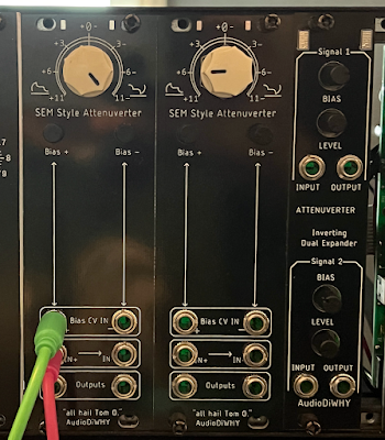
I have stopped using hook-up wire in my DiWHY builds. This means less labor since hook-up wire takes a lot of time to prep and solder.
But these wireless "skiff" builds also make it harder to modify a finished design since there are no wires to desolder and hook up to something else.
A workaround: add optional 100 mil connectors to PCBs, then connect expander modules to things like outputs and switched inputs.
Case in point: I added 100mil test points to the Attenuverter from last post.
Next I designed, laid out, and built a 4hp expander module that added 2 inverted outputs with level and bias offset control:
...the expander module (shown on the right) accommodates 2x attenuverters:
IT's.....bench photo time:
 |
| Boards were fabricated by this blog's sponsor, PCBWAY. Please help out this blog--for your next DIY build, please check 'em out. |
 |
| To fit this project onto 4HP Euro, SOIC opamps were used, I find those pretty easy to solder--use a fine tip iron, flux, and patience. |
 |
| Ready to assemble and test.... |
To connect the expander to the attenuverters, any sort of locking 100mil/2.54mm connector would have worked; I chose All Electronics CON series (CON-242 in this case) since they are relatively inexpensive and easy to get in the US.
 |
| All Electronics CON-242 Connectors |
 |
| Interconnects.... |
With all this in place it worked first time...I now have inverting outputs for each attenuverter!
...although the expander could be used for any dual CV or dual audio output to dual inverting output.
If you want to build this expander, get schematics, board layouts, Eagle files, gerbers, etc., you can get them from PCBWAY's project page, here.
For future projects: expect expanders for an expanding universe. See ya next time!


No comments:
Post a Comment